
The Metallurgy of Failing Soldered Wires
In 2026, the DIY and professional electronics landscape remains heavily split between legacy Sn63/Pb37 (Tin/Lead) and RoHS-compliant SAC305 (Tin/Silver/Copper) alloys. When troubleshooting soldered wires, understanding the metallurgy of your specific alloy is the first step in diagnosing connection failures. Sn63/Pb37 is a eutectic alloy, meaning it transitions from solid to liquid at a single temperature (183°C). SAC305, however, has a plastic phase between its solidus (217°C) and liquidus (220°C) points. If a soldered wire is moved or subjected to vibration during this plastic cooling phase, the resulting crystalline structure fractures internally, creating a classic 'cold solder joint' characterized by a dull, grainy appearance and high electrical resistance.
Furthermore, stranded wires act as massive thermal heat sinks. Attempting to solder a 14 AWG stranded wire using a micro-pencil tip on a standard 40W iron will result in the wire drawing heat away faster than the tip can replenish it. The flux burns off before the solder can properly wet the copper, leading to oxidation and catastrophic joint failure. Modern high-recovery stations like the Weller WE1010NA or Hakko FX-951 mitigate this, but technique and tip geometry remain paramount.
Troubleshooting Matrix: Diagnosing Soldered Wire Failures
| Symptom | Root Cause | Actionable Fix |
|---|---|---|
| Dull, grainy, or lumpy solder surface | Cold joint due to movement during the plastic cooling phase (common with SAC305) or insufficient heat. | Apply Kester 186 RMA flux. Reheat using a chisel tip (e.g., Hakko T18-D24) at 350°C until the solder flows smoothly, then hold perfectly still for 4 seconds. |
| Wire pulls out easily with light tug | Insufficient wetting; solder formed a mechanical wrap rather than an intermetallic compound (IMC) bond. | Desolder completely. Clean strands with isopropyl alcohol (IPA). Pre-tin the wire and the terminal separately before joining. |
| Wire insulation melted or charred back | Excessive dwell time (iron applied for >4 seconds) or using a conical tip that requires higher temperatures to transfer heat. | Switch to a bevel or wide chisel tip to maximize surface area contact. Lower temperature to 320°C for Sn63/Pb37. Strip and replace damaged wire. |
| Brittle fracture exactly at the solder edge | Mechanical fatigue due to lack of strain relief; the rigid solder joint acts as a fulcrum for bending forces. | Cut and re-strip. Apply adhesive-lined polyolefin heat shrink (e.g., 3M MDT) overlapping the insulation and the solder joint by at least 10mm. |
Step-by-Step Rework Procedure for Stranded Wires
When a soldered wire fails, simply adding more solder over the existing joint is a guaranteed path to a high-resistance failure. You must break down the joint and rebuild the metallurgical bond. According to guidelines referenced by the IPC Standards for cable assemblies, proper rework requires strict thermal and chemical management.
- Desolder and Clean: Use a high-capacity solder sucker (like the Engineer SS-02) or copper desoldering braid (Chemtronics 80-1-5) to remove the bulk of the old solder. Do not scrape the wire strands, as this damages the copper and accelerates future oxidation.
- Chemical Preparation: Apply a generous amount of mildly activated rosin flux (RMA) or a high-quality no-clean gel flux (Amtech NC-559) to the exposed strands. Never use plumbing acid flux on electrical wires; it will cause galvanic corrosion within weeks.
- Thermal Transfer: Set your station to 340°C–360°C (for SAC305) or 310°C–330°C (for Sn63/Pb37). Use a chisel tip that matches the width of the wire bundle. A 2.4mm chisel tip is ideal for 18 AWG to 14 AWG wires.
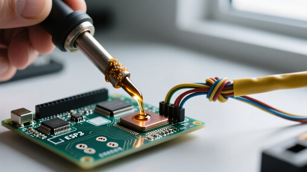
- Pre-Tinning: Touch the iron to the fluxed wire strands and feed solder directly into the strands, not onto the iron tip. Allow capillary action to draw the solder into the core of the stranded bundle. The wire should look uniformly silver, with no dry copper spots.
- The Final Joint: Pre-tin the terminal or pad. Place the pre-tinned wire against the pre-tinned pad. Apply the iron to both simultaneously. The existing solder will melt and fuse in under 2 seconds. Remove the iron and hold the wire absolutely motionless until the joint loses its liquid shine.
FAQ: Soldered Wires vs. Crimped Connections
Should I twist stranded wires tightly before soldering?
No. This is one of the most persistent myths in DIY electronics. The NASA Electronic Parts and Packaging (NEPP) Program and IPC-A-620 standards explicitly advise against tightly twisting stranded wires before soldering. Tightly twisted strands compress together, preventing flux and molten solder from penetrating the core via capillary action. This leaves the inner strands unsoldered, creating a hollow, high-resistance joint prone to internal corrosion. Lightly gathering the strands so they lay parallel is the correct technique for maximum solder wicking.
Are soldered wires safe for automotive and high-vibration environments?
Generally, no. In high-vibration environments like automotive engine bays, aerospace, or heavy machinery, crimped connections are vastly superior. Solder creates a rigid, brittle point on an otherwise flexible stranded wire. Under constant vibration, the wire will work-harden and eventually snap exactly at the edge of the solder joint. If you must use soldered wires in an automotive application (such as aftermarket stereo wiring), it is mandatory to use a mechanical strain relief. Adhesive-lined heat shrink tubing, specifically 3:1 or 4:1 shrink ratio polyolefin with an inner hot-melt adhesive wall (like Raychem RT-375), is required. When heated, the adhesive melts and bonds to the wire insulation and the solder, distributing mechanical stress across a wider area and preventing moisture ingress.
Why does my solder bead up and roll off the wire?
This is a wetting failure caused by oxidation or contamination. If the wire is old, tinned copper can develop a thick oxide layer that standard rosin flux cannot penetrate. To fix this, lightly scuff the wire with a fiberglass scratch pen or very fine 600-grit sandpaper just until the bright copper is visible, immediately apply flux to prevent flash-oxidation, and re-tin. Alternatively, if you are working with nickel-plated wires (common in high-temperature aerospace applications), standard rosin flux will fail. You must use a higher-activity RA (Rosin Activated) flux or a specialized nickel-tinning flux, followed by a thorough IPA cleaning to remove corrosive residues.
Advanced Strain Relief & Edge Cases
Troubleshooting soldered wires often extends beyond the joint itself to the physical environment the wire occupies. Here are advanced edge cases and their solutions:
- The 'Solder Wick' Effect: If solder wicks too far up the stranded wire into the insulation jacket, the wire becomes stiff and prone to snapping. To prevent this, strip exactly the length of wire needed for the terminal (usually 3mm to 6mm). If you must strip a longer length for a complex wrap, apply a tiny dab of high-temp silicone RTV or use a specialized flux stop compound at the base of the stripped section to break the capillary action.
- Multi-Strand Pigtails: When soldering two or more wires into a single terminal (a pigtail), do not solder the wires together in free air first. This creates a bulky, inflexible mass that will not seat properly in the terminal. Instead, twist the stripped ends together lightly, insert them into the terminal cup or wrap them around the post, and solder them as a single unified mass.
- High-Current DC Applications: For high-current DC applications (e.g., 12V/24V LiFePO4 battery banks, solar inverters), soldered wires are highly discouraged for the main bus connections. The high thermal mass of 4 AWG or 2 AWG battery cables requires massive amounts of heat, often melting the battery terminal's internal plastic separators or damaging the BMS (Battery Management System) solder joints. Always use hydraulic hex-crimped lugs (e.g., Amphenol SurLok Plus or Anderson Powerpole) for high-current battery connections.
Expert Tip: Always perform a 'pull test' on your first soldered wire of a new batch. A properly formed intermetallic bond on an 18 AWG copper wire should withstand approximately 20 to 25 pounds of tensile force before the copper wire itself stretches and breaks. If the wire slides out of the solder joint cleanly, your flux is dead, your temperature is too low, or the wire was oxidized prior to tinning.