
The Metallurgical Challenge of Soldering Brass to Brass
In industrial manufacturing, HVAC systems, and marine engineering, joining brass components is a daily requirement. However, soldering brass to brass presents unique metallurgical hurdles that differentiate it from standard copper-to-copper or steel-to-steel joining. Brass is primarily an alloy of copper and zinc. The presence of zinc—often ranging from 5% to 40% depending on the specific brass alloy (such as C26000 cartridge brass or C36000 free-machining brass)—drastically alters the thermal conductivity and oxide formation during the heating process.
When heating brass, zinc begins to volatilize and oxidize rapidly at temperatures exceeding 787°F (420°C), creating a stubborn zinc oxide layer that actively repels molten filler metals. Furthermore, excessive heat causes 'zinc fuming,' releasing toxic white smoke and leaving the base metal porous and structurally compromised. According to the Copper Development Association, managing this zinc oxide layer through precise thermal control and aggressive chemical fluxing is the absolute key to achieving leak-proof, high-tensile brass joints.
Critical E-E-A-T Warning: The Phosphorus Trap
Before selecting a filler metal, every industrial technician must understand a common and catastrophic error: using phosphorus-bearing alloys on brass. Alloys like Sil-Fos or Phos-Copper (which contain 5% to 8% phosphorus) are exceptional for copper-to-copper joints because the phosphorus acts as a self-fluxing agent. However, when soldering brass to brass, phosphorus reacts violently with the zinc in the brass to form zinc phosphide. This creates a highly brittle intermetallic compound at the joint interface. Under thermal cycling or mechanical vibration, a phosphorus-contaminated brass joint will experience sudden, catastrophic shear failure. Always exclude phosphorus-copper alloys when brass is involved.
Industrial Filler Metal Selection for Brass
Choosing the correct alloy depends on the operational demands of the final assembly. Industrial applications generally require either high-tin silver solders (for low-temperature, high-capillary applications) or cadmium-free silver-copper-zinc hard solders (for high-pressure, high-vibration environments).
| Alloy Classification | Industry Standard Product | Solidus / Liquidus | Tensile Strength | 2026 Est. Cost (1/2 lb) |
|---|---|---|---|---|
| Tin-Silver (Soft Solder) | Harris Stay-Brite 8 (8% Ag, 92% Sn) | 535°F / 575°F | 14,000 psi | $45 - $55 |
| Silver-Copper-Zinc (Hard) | Lucas-Milhaupt Dyna-Flo 45 (45% Ag) | 1225°F / 1375°F | 60,000 psi | $180 - $220 |
| High-Silver Cadmium-Free | Harris Silver-Flo 56 (56% Ag, 22% Cu) | 1145°F / 1205°F | 65,000 psi | $250 - $290 |
For standard instrumentation lines and low-pressure pneumatic fittings, Stay-Brite 8 remains the industry workhorse. Its low melting point prevents zinc fuming entirely, and the 8% silver content provides adequate grain refinement for strong capillary action. For high-pressure hydraulic manifolds or marine thru-hull fittings, Dyna-Flo 45 or Silver-Flo 56 is mandatory. These hard solders (often referred to as silver brazing alloys) provide tensile strengths that often exceed the base brass metal itself, ensuring the joint will not be the failure point under extreme stress.
Flux Chemistry: Breaking the Zinc Oxide Barrier
Flux is not optional when soldering brass to brass; it is a chemical necessity. The American Welding Society (AWS) categorizes fluxes by their active temperature ranges and chemical compositions. For brass, standard rosin or mild chloride fluxes are entirely insufficient for hard soldering.
- For Soft Soldering (Below 600°F): Use a highly active liquid acid flux, such as Stay-Clean Liquid Flux (zinc chloride and ammonium chloride base). This aggressively dissolves zinc oxides at low temperatures, allowing tin-silver alloys to wet the brass surface instantly.
- For Hard Soldering / Silver Brazing (1100°F - 1400°F): You must use a fluoride-based flux, such as Harris Black Flux or Stay-Silv Black Flux. The potassium fluoride and boric acid compounds in black flux remain active at high temperatures, dissolving the refractory zinc oxides that standard white paste flux (borax) cannot penetrate. The black color also acts as a visual heat indicator, turning clear and glassy when the brass reaches the optimal brazing temperature.
Heat Application: Torch vs. Induction Soldering
In 2026, industrial facilities are increasingly moving away from manual torch soldering for high-volume brass assemblies, favoring precision induction heating. Both methods have distinct operational profiles.
Air-Acetylene and Oxy-Acetylene Torch Methods
For field repairs and low-volume custom fabrication, torch soldering remains standard. When using an oxy-acetylene setup, technicians must utilize a slightly reducing (carburizing) flame rather than a strictly neutral flame. The excess unburned carbon in the reducing flame helps suppress zinc oxidation on the brass surface. Use a large, soft flame (e.g., a Victor #3 or #4 tip) to heat the entire fitting evenly. Concentrating a pinpoint, high-velocity flame on one spot will instantly melt the brass or cause severe zinc fuming before the filler metal can flow.
High-Frequency Induction Soldering
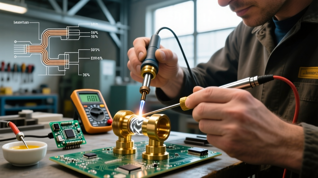
For manufacturing environments producing thousands of brass valve assemblies, RF induction heating (typically 10kW to 30kW systems operating at 10-50 kHz) provides unmatched repeatability. By designing custom copper work coils that match the geometry of the brass fitting, manufacturers can heat the joint to exactly 1350°F in under 4 seconds. When paired with automated wire feeders and optical pyrometers for closed-loop temperature control, induction soldering eliminates human error, reduces flux consumption by 40%, and completely prevents base metal overheating.
Step-by-Step Execution for Leak-Proof Brass Joints
Follow this precise sequence for manual silver soldering of brass-to-brass industrial fittings:
- Mechanical and Chemical Prep: Brass must be immaculately clean. Use a stainless steel wire brush (never carbon steel, which can embed iron particles and cause galvanic corrosion) to brighten the mating surfaces. Follow with an acetone or isopropyl alcohol wipe to remove machining oils. Free-machining brass (C36000) contains lead; ensure heavy degreasing as lead can interfere with capillary flow.
- Flux Application: Apply a generous, even coat of Black Flux to both the male and female joint surfaces. Do not skimp; the flux must completely encapsulate the joint to prevent atmospheric oxygen from reaching the heated brass.
- Pre-heating: Apply the torch flame to the heavier, more massive brass component first. Heat conducts from the heavy part to the thinner part. Keep the flame moving in a circular pattern.
- Filler Metal Introduction: Once the flux turns clear and glassy (indicating the brass is near 1100°F), withdraw the flame slightly and touch the silver solder wire to the joint edge. Do not melt the wire with the torch; the heat of the brass itself must melt the alloy. If the wire balls up and rolls off, the brass is not hot enough or the flux has failed.
- Capillary Draw and Quenching: Allow the alloy to be drawn entirely through the joint via capillary action. Once a continuous fillet is visible around the entire perimeter, remove the heat immediately. Allow the assembly to cool naturally until the flux turns black and solidifies, then quench in warm water to thermal-shock the glassy flux residue off the brass.
Troubleshooting Matrix: Common Brass Soldering Failures
Even experienced technicians encounter issues when joining brass. Use this diagnostic matrix to identify and correct joint failures.
| Failure Symptom | Root Cause | Corrective Action |
|---|---|---|
| Filler metal balls up and refuses to wet the brass | Insufficient base metal temperature or exhausted flux | Increase heat input; re-apply fresh fluoride flux; ensure surfaces are chemically degreased. |
| White smoke (fuming) during heating | Excessive localized heat causing zinc volatilization | Switch to a larger, softer torch tip; keep the flame moving; consider a lower-temperature tin-silver alloy. |
| Joint leaks under pressure testing | Flux inclusions trapped inside the capillary space | Apply less flux inside the male fitting; ensure proper joint clearance (0.002 to 0.005 inches) to allow flux to be pushed out by the alloy. |
| Brittle joint that cracks upon cooling | Use of phosphorus-bearing alloy (Sil-Fos) on brass | Discard the joint entirely. Grind out the filler and re-braze using a cadmium-free silver-copper-zinc alloy. |
Final Thoughts on Industrial Brass Joining
Soldering brass to brass in demanding industrial applications requires a departure from standard copper plumbing techniques. By respecting the metallurgical limitations of zinc, strictly avoiding phosphorus-bearing alloys, and utilizing aggressive fluoride-based fluxes paired with precise thermal management, technicians can produce joints that withstand extreme pressures, corrosive marine environments, and relentless vibration. As the Harris Products Group frequently notes in their technical literature, the success of a brazed or soldered brass assembly is determined 90% by surface preparation and flux chemistry, and only 10% by the actual application of the filler metal. Invest in high-quality silver-bearing alloys and rigorous cleaning protocols, and your brass joints will consistently outperform the base materials themselves.