
The Metallurgy of Soldered Metal: Understanding Joint Failures
When troubleshooting electronics or plumbing, it is crucial to understand that a successful joint is not merely melted metal resting on a surface; it is a complex metallurgical diffusion process. When soldered metal bonds to a copper pad or component lead, it forms an Intermetallic Compound (IMC) layer. In standard tin-copper systems, this layer consists of Cu6Sn5 (eta phase) and Cu3Sn (epsilon phase).
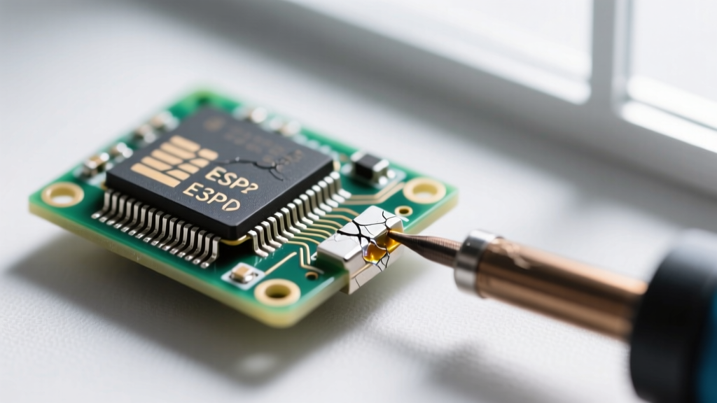
While a thin IMC layer (1 to 3 micrometers) is necessary for a strong electrical and mechanical bond, excessive heat or prolonged thermal aging causes the Cu3Sn layer to grow thicker. This overgrowth creates microscopic gaps known as Kirkendall voids, which act as stress concentrators and inevitably lead to brittle fractures in the soldered metal under mechanical or thermal stress.
Common Solder Alloys and Their Failure Profiles
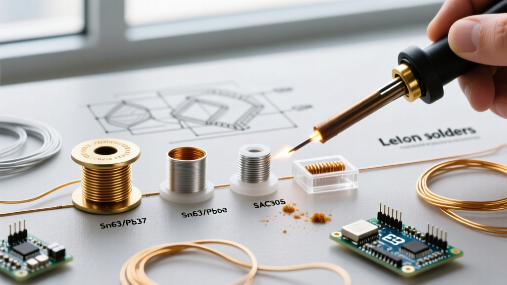
Choosing the right alloy dictates your troubleshooting approach. Below is a comparison of the most common alloys used in modern electronics and structural applications.
| Alloy Designation | Composition | Melting Point | Primary Use Case | Common Failure Mode |
|---|---|---|---|---|
| SAC305 | Sn96.5 / Ag3.0 / Cu0.5 | 217°C - 220°C | Commercial Lead-Free PCB Assembly | Thermal fatigue cracking, brittle drop-shock fractures |
| Sn63/Pb37 | Tin 63% / Lead 37% | 183°C (Eutectic) | Aerospace, Medical, Hobbyist | Tin whisker growth, thermal creep |
| Sn96.5/Ag3.5 | Tin 96.5% / Silver 3.5% | 221°C | High-Temp / High-Reliability | Silver leaching from component pads |
| Sn42/Bi58 | Tin 42% / Bismuth 58% | 138°C (Eutectic) | Low-Temp / Heat-Sensitive Parts | Extreme brittleness, poor vibration resistance |
Troubleshooting FAQ: Diagnosing Soldered Metal Defects
Field failures and workbench mistakes often manifest in distinct visual and electrical ways. Here are the most frequent questions regarding compromised soldered metal connections.
Q: Why is my soldered metal joint dull, grainy, or rough?
Diagnosis: Disturbed Joint or Cold Joint.
Technical Breakdown: If you are using a non-eutectic alloy like SAC305, the solder passes through a "plastic" or "pasty" range between its solidus (217°C) and liquidus (220°C) temperatures. If the component or wire moves during this 3-degree window, the crystalline structure fractures as it forms, resulting in a dull, grainy appearance. For eutectic alloys (Sn63/Pb37), a dull joint almost always indicates insufficient heat transfer (a true cold joint) where the flux activated but the base metal never reached the alloy's melting point, preventing IMC formation.
The Fix: Do not simply add more solder. Apply fresh liquid or tacky flux (e.g., Amtech NC-559-V2-TF) and reflow the joint with an iron set to 350°C for SAC305 or 320°C for Sn63/Pb37, ensuring the tip contacts both the pad and the lead simultaneously for 2-3 seconds.
Q: Why does the soldered metal connection crack under vibration or thermal cycling?
Diagnosis: Coefficient of Thermal Expansion (CTE) Mismatch and Lack of Strain Relief.
Technical Breakdown: When soldered metal bridges two materials with vastly different CTEs (e.g., a silicon chip, a copper leadframe, and an FR4 fiberglass board), temperature changes cause them to expand and contract at different rates. This induces shear stress on the solder fillet. Over hundreds of thermal cycles, micro-cracks initiate at the heel or toe of the joint and propagate through the bulk solder or the IMC layer.
The Fix: For through-hole components, ensure a proper clinch (bending the lead over the pad) before soldering to provide mechanical support. For surface mount or heavy wires, apply a high-modulus RTV silicone or epoxy underfill (like Loctite 4983) to absorb mechanical shock and distribute shear forces away from the soldered metal.
Q: How do I fix a soldered metal joint that repels new solder (de-wetting)?
Diagnosis: Severe Oxidation or Flux Exhaustion.
Technical Breakdown: De-wetting occurs when the molten solder initially coats the surface but then pulls back into islands, leaving exposed, oxidized base metal. This is common when attempting to rework old soldered metal that has been exposed to high humidity or when using an iron tip that is heavily oxidized (blackened). The flux in your core wire is consumed before it can reduce the heavy copper oxides.
Advanced Troubleshooting: Flux Residue and Dendritic Growth
A hidden failure mode in soldered metal assemblies is electromigration. Many technicians assume "no-clean" fluxes are entirely benign. However, under high-humidity and high-bias voltage conditions, uncleaned rosin or organic acid residues can become conductive. This leads to dendritic growth—microscopic metallic trees that bridge adjacent soldered metal pads, causing intermittent short circuits.
- Symptom: Circuit works perfectly on the bench but fails randomly in humid environments or draws excess micro-amps in sleep mode.
- Verification: Inspect the board under a 10x-40x stereo microscope. Look for white, powdery, or fern-like crystalline structures between soldered metal joints.
- Remediation: Clean the assembly using an electronics-grade solvent like MG Chemicals 413A (Isopropyl Alcohol) or a dedicated saponifier for water-soluble fluxes, followed by ultrasonic agitation if component tolerances permit.
Step-by-Step Recovery: Reworking Failed Soldered Metal
When a soldered metal joint fails inspection per IPC-A-610 standards (the globally recognized benchmark for electronic assembly acceptability), proper rework is mandatory. Follow this precise protocol to restore joint integrity without damaging the PCB laminate.
- Pre-Heat and Flux: Apply a generous amount of tacky flux to the defective soldered metal. Flux lowers the surface tension and prevents further oxidation during the extended heat cycle required for rework.
- Desoldering Braid Application: Use a high-quality copper wick (e.g., Chemtronics 20-2000-10). Place the wick over the joint and apply your iron (set to 380°C) on top of the wick. Never drag the iron directly on the pad. Allow capillary action to draw the molten solder into the braid. Remove both simultaneously to prevent cold-sticking.
- Pad Leveling: Inspect the copper pad. If residual solder remains, use a vacuum desoldering tool (like the Hakko FR-301) to pull the remaining soldered metal from the barrel (for through-hole) or re-wick the surface pad until it is flat.
- Component Placement and Reflow: Tin the pad lightly with fresh SAC305 wire. Place the component, apply heat to the lead and pad simultaneously, and feed a minimal amount of new solder to form a smooth, concave fillet. The ideal wetting angle should be less than 90 degrees.
- Inspection: Verify the joint against IPC Class 2 or Class 3 requirements. The soldered metal must exhibit a smooth, shiny (or matte, for lead-free) continuous fillet with no visible cracks, voids, or non-wetted areas.
Preventative Maintenance for Long-Lasting Soldered Metal
The longevity of any soldered metal connection relies heavily on the initial thermal profile and tool maintenance. According to the rigorous guidelines outlined in NASA-HDBK-8739.3 (NASA's standard for soldered electrical connections), the time a joint is held above the solder's melting point should be strictly minimized—ideally under 4 seconds per joint.
Prolonged heat application not only degrades the flux but also accelerates the growth of the brittle Cu3Sn IMC layer and risks delaminating the copper pad from the FR4 substrate. Invest in a temperature-controlled station (such as the Weller WE1010NA or Hakko FX-888D, both priced around $110-$130) rather than a cheap unregulated wand. Unregulated wands can spike to over 450°C when idle, instantly oxidizing the tip and scorching the flux upon contact, guaranteeing a compromised soldered metal joint.
"A reliable soldered metal joint is the result of controlled chemistry and precise thermodynamics, not just melted wire. Respect the flux, control the heat, and trust the metallurgy." — Senior IPC Certified Trainer
By understanding the metallurgical realities of IMC formation, recognizing the visual cues of thermal fatigue, and adhering to strict rework protocols, you can diagnose and permanently resolve virtually any failure in soldered metal assemblies.