
The Metallurgy of Tin Soldering: Eutectic vs. Lead-Free
Tin soldering remains the undisputed backbone of modern electronics assembly. Whether you are prototyping a custom microcontroller board or repairing vintage audio equipment, understanding the metallurgy of tin-based alloys is the difference between a reliable, glossy joint and a high-resistance failure point. As we navigate the component shortages and shifting material costs of 2026, selecting the right tin alloy requires balancing melting points, mechanical strength, and budget.
Decoding the Alloys: Sn63/Pb37 vs. SAC305 vs. SnCu
The transition away from leaded solders, driven by the EU RoHS Directive, fundamentally changed how we approach tin soldering. However, leaded alloys remain legal and highly preferred for non-commercial DIY, aerospace, and medical prototypes due to their superior wetting characteristics and lower thermal stress on components.
| Alloy Designation | Composition | Solidus / Liquidus | Characteristics & 2026 Pricing |
|---|---|---|---|
| Sn63/Pb37 | 63% Tin, 37% Lead | 183°C / 183°C (Eutectic) | Zero pasty range. Glossy finish. Approx. $30-$35/lb. Ideal for DIY and hand soldering. |
| SAC305 | 96.5% Sn, 3.0% Ag, 0.5% Cu | 217°C / 220°C | Industry standard lead-free. High tensile strength. Pasty range risks disturbed joints. Expensive ($50+/lb due to silver spot prices). |
| Sn99.3/Cu0.7 | 99.3% Tin, 0.7% Copper | 227°C / 227°C (Eutectic) | Budget lead-free alternative. Dull finish. Higher melting point requires aggressive flux. Approx. $25/lb. |
Expert Insight: The 'pasty range' of SAC305 (the 3-degree window between solidus and liquidus) is a notorious trap for beginners. If the PCB or component moves while the solder is in this semi-solid plastic state, it creates a 'disturbed joint'—a grainy, fractured connection that will inevitably fail under thermal cycling.
Choosing the Right Flux Chemistry for Tin
Tin oxidizes rapidly when exposed to the heat of a soldering iron. Without flux, the molten tin will ball up and refuse to wet the copper pad. The flux dissolves the metal oxides, allowing metallurgical bonding (intermetallic compound formation). According to the IPC J-STD-001 standards, flux selection must match your cleaning capabilities and end-use environment.
- Rosin Mildly Activated (RMA): The gold standard for hobbyists. Kester 282 or 245 series provides excellent wetting and leaves a hard, non-conductive residue that can be left on the board or cleaned with 99% Isopropyl Alcohol (IPA).
- No-Clean (NC): Formulated with synthetic resins (like Kester 331). The residue is designed to be left on the PCB. However, if you use excessive heat, the flux can scorch, turning brown and becoming slightly corrosive over time.
- Water-Soluble (OA): Highly active organic acid fluxes (e.g., Alpha Metals WS-33). Excellent for heavily oxidized through-hole components, but must be washed off with distilled water immediately after soldering to prevent catastrophic copper trace corrosion.
Temperature Profiles and Iron Calibration
A common misconception is that turning the iron to maximum heat speeds up the tin soldering process. In reality, excessive heat vaporizes the flux before it can clean the pad, leading to cold, oxidized joints. Modern digital stations like the Hakko FX-888D or Weller WE1010 require specific setpoints based on the alloy and thermal mass of the joint.
Optimal Setpoints for 0.031-inch (0.8mm) Wire
- Sn63/Pb37 (Standard Pads): 340°C - 350°C
- Sn63/Pb37 (Large Ground Planes): 370°C (or use a pre-heater to avoid delaminating the PCB)
- SAC305 (Standard Pads): 360°C - 380°C
- Sn99.3/Cu0.7 (Standard Pads): 380°C - 390°C
Pro Tip: Always use a chisel tip (e.g., Hakko T18-D12) rather than a conical tip for through-hole and standard SMD tin soldering. The flat surface area maximizes thermal transfer, reducing the time the iron needs to dwell on the pad.
Step-by-Step Tin Soldering Technique
Follow this precise sequence to ensure a flawless intermetallic bond every time:
- Prep the Surfaces: Wipe the PCB pads and component leads with 99% IPA and a lint-free wipe to remove finger oils.
- Tin the Iron: Apply a sacrificial coat of fresh solder to the tip. This creates a thermal bridge. Wipe the tip on a damp brass sponge immediately before touching the joint.
- Heat the Joint: Place the tinned tip so it simultaneously touches the copper pad and the component lead. Hold for exactly 1 second.
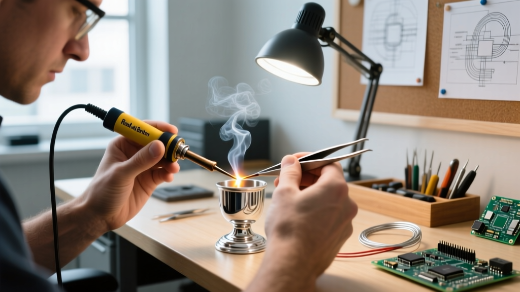
- Feed the Wire: Introduce the solder wire to the joint, not the iron tip. If the joint is hot enough, the flux will activate (you will see a tiny wisp of smoke) and the solder will flow smoothly via capillary action. Feed for 1 to 2 seconds.
- Withdraw in Order: Remove the solder wire first, then sweep the iron away at a 45-degree angle. Hold the board perfectly still for 3 seconds while the joint solidifies.
Troubleshooting and Edge Cases
Even experienced engineers encounter defects. Here is how to diagnose and correct the most common tin soldering anomalies.
1. The Grainy or Disturbed Joint
Visual Cue: The solder joint looks dull, rough, or has visible ridges instead of a smooth, concave fillet. Root Cause: Movement during the solidification phase, or using a non-eutectic lead-free alloy without adequate fixturing. Correction: Re-flow the joint with a fresh drop of Sn63/Pb37 or add a generous amount of liquid RMA flux and re-heat until fully molten, then hold strictly still.
2. Non-Wetting and Solder Balling
Visual Cue: Solder rolls off the pad into tiny spheres, refusing to stick to the copper. Root Cause: Severe oxidation on the PCB pads (common with boards stored for >6 months) or expired solder wire where the internal flux core has dried out. Correction: Lightly abrade the pad with a fiberglass scratch pen. Apply external tacky flux (like Amtech NC-559) before attempting to solder again.
3. The Tin Whisker Phenomenon
A highly specific edge case in modern electronics involves pure tin finishes. According to extensive research by the NASA Electronic Parts and Packaging (NEPP) Program, pure tin-plated components can spontaneously grow microscopic, crystalline 'whiskers' over time. These conductive filaments can bridge adjacent traces, causing catastrophic short circuits in high-reliability systems.
Mitigation for DIYers: If you are building aerospace, automotive, or high-voltage equipment, avoid components with matte pure-tin finishes. Opt for components with a Tin-Lead (SnPb) dip, or use a SnAgCu (SAC) solder alloy, as the addition of lead or bismuth significantly inhibits whisker growth. For standard 5V consumer DIY projects, tin whiskers are generally a non-issue within the product's usable lifespan.
Final Thoughts on Tool Maintenance
Your soldering iron tip is a consumable, but its lifespan is dictated by your maintenance habits. Never leave a tinning station idle at 380°C for more than 10 minutes; the iron plating will oxidize and pit, rendering it useless. Always turn the station down to 150°C when stepping away, and ensure the tip is heavily coated with a thick blob of flux-core solder before powering down. By respecting the metallurgy of tin alloys and the chemistry of fluxes, your PCB assemblies will achieve professional-grade reliability.