
The Dual Meaning of Heat Sink Soldering
When veteran engineers and modern hobbyists discuss heat sink soldering, they are usually referring to one of two distinctly different practices. Historically, it meant using a physical heat sink (a thermal shunt) during the soldering process to protect sensitive semiconductor junctions from thermal runaway. In modern power electronics, however, it refers to the act of soldering a power component directly to a heat sink or substrate for maximum thermal dissipation.
Understanding the evolution of both practices is critical for anyone building high-power audio amplifiers, RF transmitters, or modern EV inverter circuits in 2026. The transition from basic clip-on shunts to advanced sintered silver die-attach techniques represents one of the most fascinating metallurgical journeys in electronics manufacturing.
Era 1: The Thermal Shunt and the Clip-On Age (1950s–1980s)
In the early days of solid-state electronics, germanium transistors (like the legendary AC128) and early silicon power devices (such as the 2N3055 in TO-3 packages) were highly susceptible to thermal damage. The melting point of standard Sn60Pb40 solder is 183°C, but the maximum junction temperature for many early germanium devices was barely 85°C.
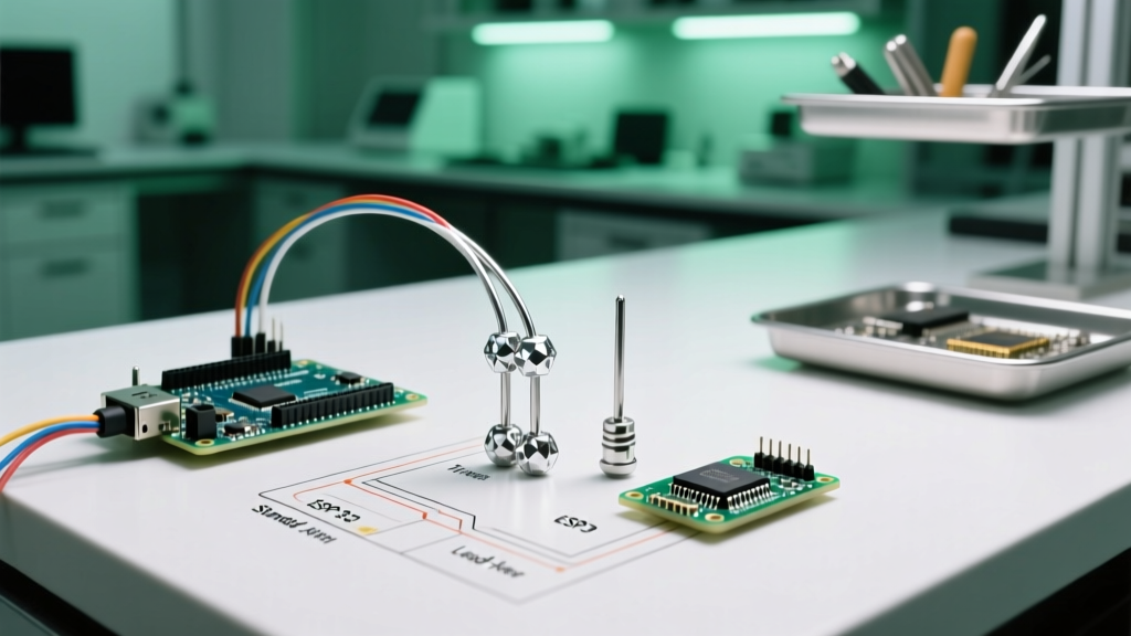
To prevent the heat from the soldering iron from traveling up the copper leads and destroying the silicon or germanium die, technicians relied on thermal shunts.
- Copper Braids and Alligator Clips: Technicians would clamp heavy copper alligator clips or wrap desoldering braid around the transistor lead, positioning it exactly between the solder joint and the transistor body. The copper acted as a heat sink, absorbing the thermal energy before it reached the sensitive junction.
- Wet Sponges: In field repairs, a wet sponge or damp cloth was often wrapped around the component body as a crude, evaporative heat sink.
This era was defined by the IPC-A-610 workmanship standards, which heavily emphasized the use of heat sinks on leads of thermally sensitive components during wave and hand soldering.
Era 2: The Mechanical Shift and the CTE Problem (1990s–2010s)
As power electronics evolved into the TO-220 and TO-247 packages, the industry faced a massive challenge with soldering components directly to aluminum or copper chassis heat sinks. The culprit was the Coefficient of Thermal Expansion (CTE).
Silicon has a CTE of roughly 2.6 µm/m·°C. Aluminum, the most common heat sink material, has a CTE of 23 µm/m·°C. When a soldered joint undergoes thousands of thermal cycles (heating up during operation and cooling down at rest), the aluminum expands and contracts at nearly ten times the rate of the silicon die. This CTE mismatch causes severe shear stress on the solder joint, leading to creep fatigue, micro-cracking, and eventual thermal failure.
The Rise of Thermal Interface Materials (TIMs)
Because direct heat sink soldering was causing field failures in consumer electronics and early computer power supplies, the industry pivoted to mechanical mounting paired with Thermal Interface Materials:
- Mica and Silicone Pads: The Bergquist Sil-Pad (introduced in the 1980s but ubiquitous by the 1990s) allowed for electrical isolation and mechanical compliance.
- Thermal Greases: Pastes like Arctic Silver Céramique filled microscopic air gaps without creating a rigid, stress-inducing bond.
- Spring Clips and Screws: Mechanical force replaced metallurgical bonds, allowing the component to 'float' slightly and absorb CTE expansion without cracking.
Era 3: The Power Electronics Renaissance (2015–Present)
Fast forward to the mid-2010s and the 2026 landscape of wide-bandgap semiconductors. Silicon Carbide (SiC) and Gallium Nitride (GaN) MOSFETs are now standard in 800V EV architectures and high-density RF amplifiers. These devices operate at junction temperatures exceeding 175°C and generate massive heat fluxes. Traditional TIMs (which typically offer thermal conductivities of only 1 to 3 W/mK) are now too thick and thermally resistive for modern die-attach applications.
Consequently, heat sink soldering is back, but it has evolved into highly advanced metallurgical processes like Transient Liquid Phase (TLP) bonding and sintered silver.
Comparison of Modern Heat Sink Attachment Methods
| Attachment Method | Thermal Conductivity | Max Operating Temp | CTE Mismatch Tolerance | Primary Use Case |
|---|---|---|---|---|
| Sn63Pb37 (Eutectic) | ~50 W/mK | 125°C | Poor (Prone to fatigue) | Vintage audio, low-power DIY |
| SAC305 (Lead-Free) | ~64 W/mK | 150°C | Moderate | Standard PCB assembly |
| Sintered Silver (e.g., Heraeus) | ~150 to 200 W/mK | >300°C | Excellent (High creep resistance) | SiC/GaN Die Attach, EV Inverters |
| Thermal Epoxy (e.g., Arctic Alumina) | ~9 W/mK | 150°C | Good (Compliant) | DIY LED stars, small RF shields |
| Advanced TIM Pads | 3 to 12 W/mK | 200°C | Excellent (Mechanically decoupled) | CPU/GPU cooling, TO-247 mounting |
Advanced Techniques: Sintered Silver and TLP Bonding
For industrial applications, companies like Heraeus Electronics and Semikron-Danfoss have pioneered sintered silver die-attach. Unlike traditional soldering, which relies on melting a bulk alloy, sintering uses nanoscale silver particles suspended in an organic carrier.
- The Process: The paste is applied to the substrate, the die is placed, and pressure (10–30 MPa) and heat (200°C–250°C) are applied.
- The Magic: Due to the high surface area of the nanoparticles, the silver particles fuse (sinter) together at temperatures far below the bulk melting point of silver (961°C).
- The Result: A joint that is processed at 230°C but will not melt until it reaches 961°C, offering unmatched thermal conductivity and reliability for high-heat flux SiC modules.
Practical Guide for DIYers and Prosumers in 2026
While hobbyists do not have access to 30 MPa hydraulic sintering presses, the principles of heat sink soldering remain highly relevant for high-end DIY projects like Class-D audio amplifiers, high-power LED arrays, and ham radio RF amplifiers.
When to Solder Directly vs. Use TIMs
Scenario A: Building a Gainclone (LM3886 Audio Amplifier)
If you are using the non-isolated LM3886T, you cannot solder it directly to an aluminum heat sink without shorting your circuit. You must use a mica or silicone insulator pad with thermal grease. However, if you are soldering a copper heat spreader to a raw aluminum chassis, standard Sn60Pb40 solder will not wet the aluminum due to the instant formation of aluminum oxide. You must use a specialized zinc-based flux or opt for a high-thermal-conductivity epoxy like Arctic Alumina.
Scenario B: High-Power LED Star PCBs (Cree XLamp)
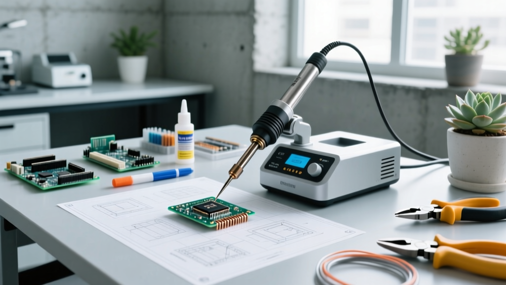
When attaching a copper LED star board to a massive finned heat sink, soldering is superior to thermal paste because it eliminates the 'pump-out' effect (where thermal cycling pushes grease out from the center). Use a high-wattage station (like the Weller WX2021 with a massive chisel tip) or a hotplate to pre-heat the heat sink to 100°C, apply Sn96.5/Ag3.0/Cu0.5 (SAC305) flux-cored solder, and clamp the star board flat until the joint solidifies.
Troubleshooting Common Heat Sink Soldering Failures
The 'Oil-Canning' Effect: When soldering large surface areas (like a DBC substrate to a baseplate), the center of the joint cools slower than the edges. As the center finally contracts, it pulls the metal inward, creating a concave 'dish' shape. This causes severe internal stress and can literally crack the ceramic substrate.
How to avoid it: Use a controlled pre-heating profile. Never let a large heat sink cool in free air; place it on an insulating ceramic block to slow the cooling rate and allow the solder joint to anneal naturally, relieving internal shear stresses.
Conclusion
The evolution of heat sink soldering is a testament to the shifting demands of electronics. We moved from protecting fragile germanium junctions with copper clips, to abandoning solder entirely in favor of mechanical TIMs, and finally back to advanced metallurgical bonds like sintered silver to tame the immense heat of modern SiC and GaN devices. Whether you are clamping a thermal shunt on a vintage transistor or reflowing a copper slug to an RF amplifier chassis, understanding the thermal and mechanical forces at play is the key to building reliable, long-lasting electronics.