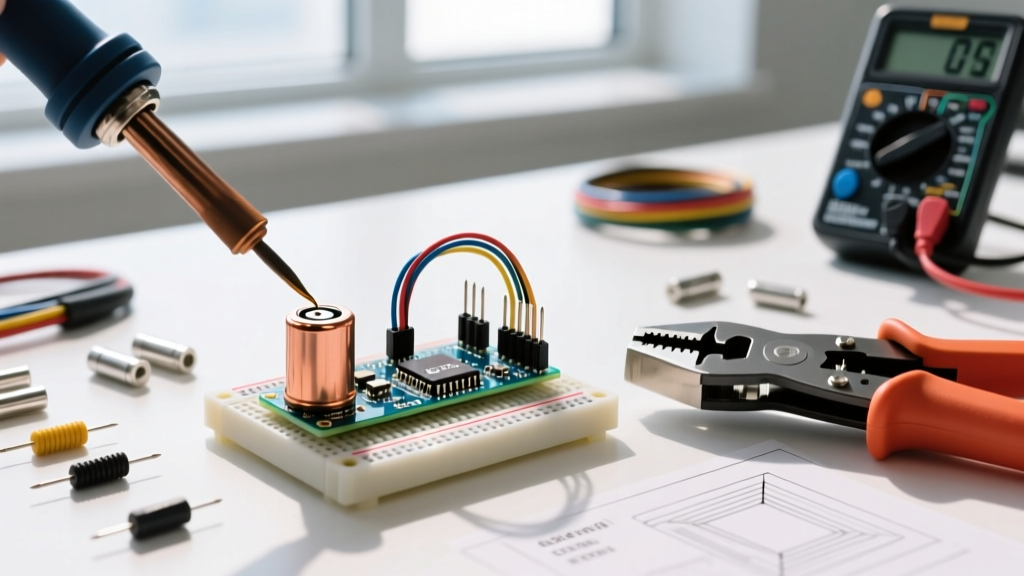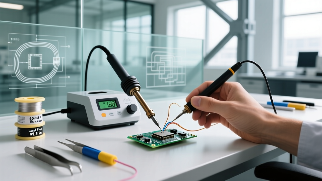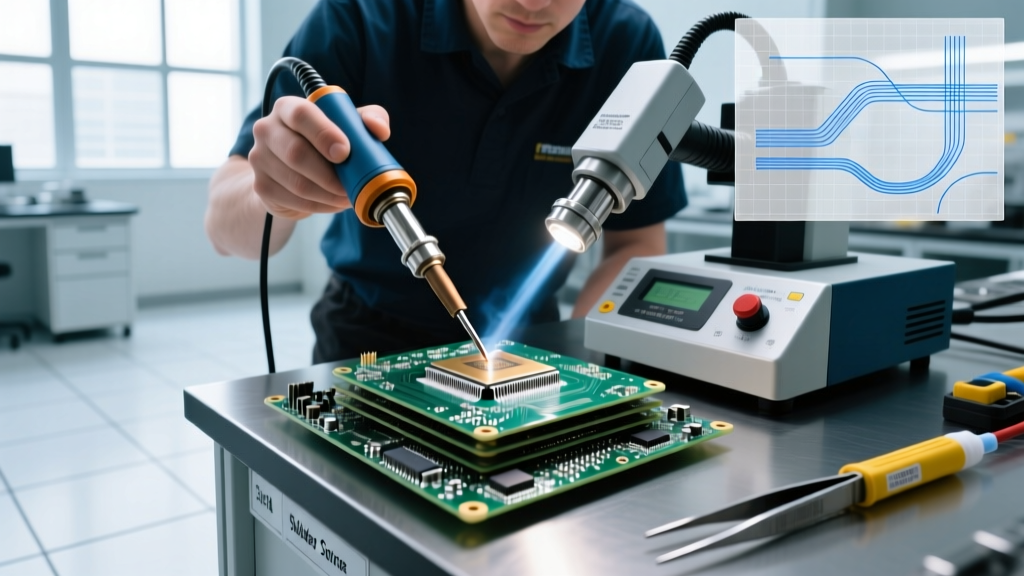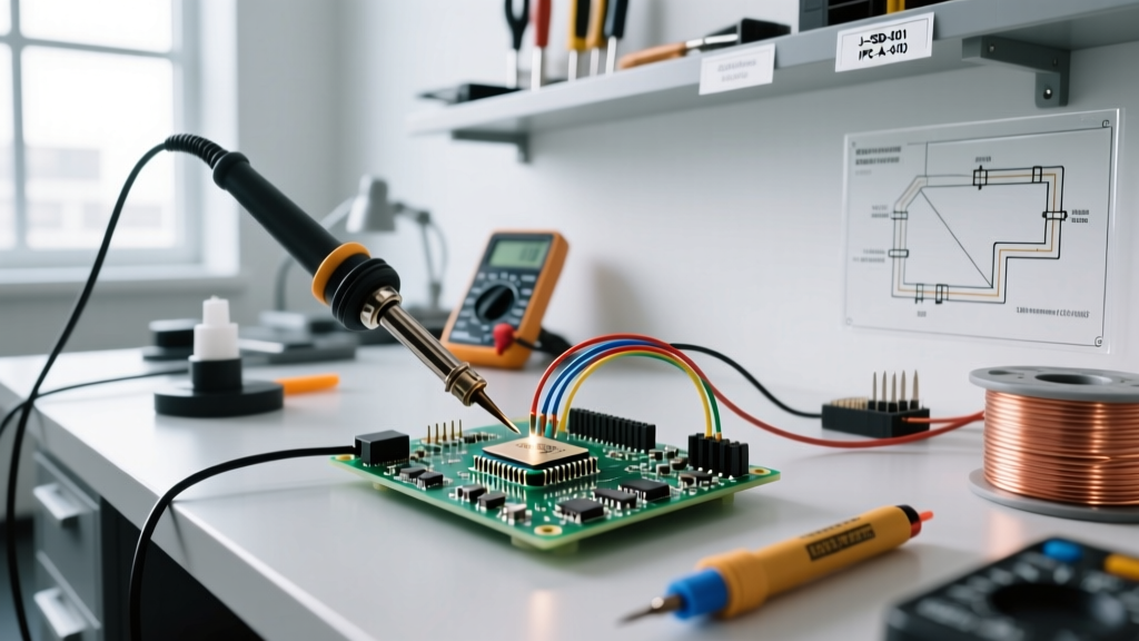

Despite the overwhelming dominance of Surface Mount Technology (SMT) in modern consumer electronics, THT soldering (Through-Hole Technology) remains an irreplaceable pillar of electronic manufacturing in 2026. While SMT offers miniaturization and automated assembly speed, THT provides unmatched mechanical strength, superior thermal dissipation, and ease of manual prototyping. For electrical engineers, DIY enthusiasts, and contract manufacturers, knowing exactly when to specify through-hole components versus surface mount is a critical design decision that impacts product reliability, manufacturing cost, and lifecycle longevity.
This comprehensive decision framework will guide you through the engineering, environmental, and practical considerations of THT soldering, helping you select the right applications, equipment, and metallurgical alloys for your next printed circuit board (PCB) assembly.
The Core THT Soldering Decision Matrix
Before committing to a through-hole design, evaluate your project against this comparative matrix. This framework isolates the specific scenarios where THT soldering outperforms SMT.
| Design Factor | THT Soldering | SMT Assembly | Decision Winner |
|---|---|---|---|
| Mechanical Stress & Vibration | Excellent (leads anchor through board) | Poor to Fair (relies on surface pad adhesion) | THT |
| High-Current / High-Power | Superior thermal mass and current capacity | Limited by trace width and pad size | THT |
| Prototyping & Rework | Easy manual insertion and desoldering | Requires hot air, stencils, and microscopes | THT |
| Miniaturization & Density | Poor (requires drilled holes, large footprints) | Excellent (components on both sides) | SMT |
| High-Volume Automated Cost | Higher (drilling and wave soldering costs) | Lower (pick-and-place and reflow) | SMT |
Phase 1: Application and Environmental Stress Assessment
The primary justification for THT soldering is mechanical integrity. When a PCB is subjected to severe physical shock, continuous vibration, or extreme thermal cycling, surface mount pads can delaminate or crack. Through-hole leads, however, pass entirely through the FR4 substrate and are secured by a solid column of solder, distributing mechanical stress across the entire thickness of the board.
Adhering to Aerospace and Defense Standards
In mission-critical environments, THT is often mandated by strict workmanship standards. According to the NASA Workmanship Standards for soldered electrical connections, through-hole components are required for high-vibration aerospace applications where SMT solder joints would fatigue and fail. Similarly, military and medical devices frequently specify THT for heavy connectors, large electrolytic capacitors, and power transformers that would easily rip SMT pads off the board during cable mating or physical impacts.
Understanding Barrel Fill Requirements
A critical metric in THT soldering is the barrel fill percentage—the amount of solder that wicks up the plated through-hole (PTH). The IPC-A-610 standard for acceptability of electronic assemblies defines strict criteria for this:
- Class 2 (Standard Electronics): Requires a minimum of 75% barrel fill. This is acceptable for consumer goods and standard industrial controls.
- Class 3 (High-Reliability): Requires 100% barrel fill with a continuous fillet on both the top and bottom sides of the board. This is mandatory for life-support, aerospace, and automotive safety systems.
Expert Insight: Achieving 100% barrel fill on a ground-plane-connected pin requires significant thermal energy. If your THT pin is connected to a large copper pour without thermal relief spokes, the copper will act as a massive heat sink, pulling heat away from the joint and resulting in a cold solder joint or incomplete barrel fill. Always use thermal relief pads for THT connections to internal ground planes.
Phase 2: Equipment Selection Framework for THT
THT soldering demands higher thermal recovery than SMT. Because the component lead and the plated barrel act as heat sinks, your soldering station must deliver rapid, sustained wattage to maintain the tip temperature during the 2 to 4 seconds required to properly wet a through-hole joint. Here is the 2026 equipment decision tree based on user profiles and budget.
Tier 1: The Hobbyist and Prototyper (Under $150)
For DIY electronics, Arduino projects, and low-volume prototyping, a reliable 65W to 70W station is sufficient.
- Hakko FX-888D ($110 - $120): The undisputed king of entry-level THT. It features a 65W ceramic heater and digital temperature control. For THT, swap the default conical tip for a Hakko D24 (Chisel) or D12 (Bevel) tip to maximize surface area contact with the lead and pad.
- Weller WE1010NA ($135 - $145): Offers 70W of power, providing slightly faster thermal recovery than the Hakko when soldering large electrolytic capacitors or thick wire harnesses.
Tier 2: The Professional Technician ($200 - $400)
For repair technicians and small-batch production, active tip technology is mandatory. Active tips integrate the heater directly into the tip itself, eliminating the thermal lag of traditional ceramic heaters.
- Weller WX2021 ($350+): A dual-channel powerhouse. The 200W power unit ensures that even when soldering heavy 10AWG wires to massive THT binding posts, the tip temperature never drops below the setpoint.
- Pace ADS200 ($250 - $300): Features the AccuDrive heating system, offering exceptional sensitivity and instantaneous heat delivery for complex multi-layer THT boards.
Tier 3: High-Reliability and Industrial ($500+)
When soldering Class 3 aerospace boards or heavy industrial power supplies, JBC is the industry standard.
- JBC CD-2BQF ($650+): Utilizes JBC's exclusive heating system where the tip reaches 350°C in under 2 seconds. The Hakko FX-888D is great for beginners, but JBC's 130W T245 handpiece provides the sheer thermal mass required to solder 14-layer PCBs with heavy internal ground planes without preheating the board.
Phase 3: Solder Alloy and Flux Decision Tree
The metallurgical composition of your solder wire dictates the wetting behavior, joint strength, and required iron temperature. Select your alloy based on your regulatory constraints and application environment.
| Alloy Type | Composition | Melting Point | Ideal Tip Temp | Best Use Case |
|---|---|---|---|---|
| Eutectic Leaded | Sn63/Pb37 | 183°C (361°F) | 300°C - 330°C | Prototyping, hobbyist, non-RoHS repair. Excellent wetting and shiny joints. |
| Lead-Free SAC | SAC305 (Sn96.5/Ag3.0/Cu0.5) | 217°C (423°F) | 340°C - 380°C | Commercial production, RoHS compliant. Requires higher heat and active flux. |
| High-Reliability Leaded | Sn62/Pb36/Ag2 | 179°C (354°F) | 300°C - 330°C | Aerospace, military. Silver prevents silver leaching from component terminations. |
Flux Chemistry Selection
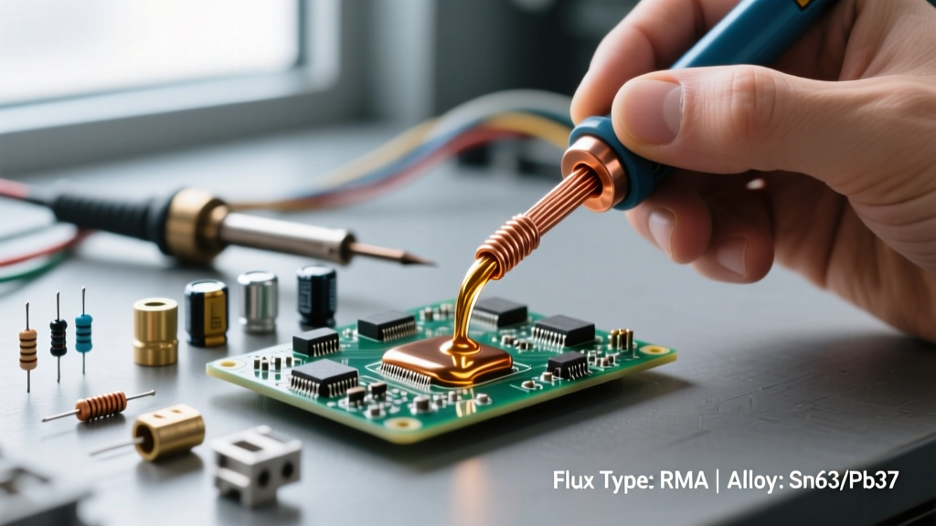
For manual THT soldering, the flux core inside your solder wire does the heavy lifting. Rosin Mildly Activated (RMA) is the gold standard for through-hole work. It provides excellent oxide removal and leaves a benign residue that is easy to clean with isopropyl alcohol. Avoid No-Clean fluxes for dense THT boards unless you are certain the residue will not trap moisture or cause electrochemical migration (dendrite growth) in high-humidity environments.
Troubleshooting Common THT Failure Modes
Even with the right equipment, THT soldering presents unique physical challenges. Use this troubleshooting guide to diagnose and correct common defects.
1. Incomplete Barrel Fill (Cold Joint)
Symptom: Solder wets the bottom pad but fails to wick up the barrel to the top layer. The joint looks dull and bulbous.
Root Cause: Insufficient thermal energy. The internal copper planes are sinking the heat.
Solution: Increase your iron temperature by 20°C. Apply the chisel tip simultaneously to the component lead and the pad for 3 full seconds before feeding the solder wire. If the board has heavy ground planes, use a bottom-side PCB preheater set to 100°C to reduce the thermal delta.
2. Pad Lifting and Delamination
Symptom: The copper annular ring separates from the FR4 fiberglass substrate during soldering.
Root Cause: Excessive dwell time. Holding a 380°C iron on a pad for more than 5 seconds degrades the epoxy resin binding the copper to the board.
Solution: Never exceed 4 seconds of dwell time per joint. If the solder does not flow within 4 seconds, remove the iron, let the board cool for 10 seconds, apply fresh liquid flux, and try again with a wider, higher-mass tip.
3. Solder Wicking (Solder Starvation)
Symptom: Solder flows up the component lead and away from the PCB pad, leaving a weak mechanical connection at the board level.
Root Cause: The iron was applied to the component lead before the PCB pad reached soldering temperature. Heat travels up the lead, pulling the molten solder with it.
Solution: Always touch the iron tip to the pad first, then slide it slightly to touch the lead, and feed the solder directly into the pad-lead intersection. Ensure your component leads are properly clinched (bent) to hold the part flush against the board before soldering.
Final Verdict: Integrating THT into Modern Workflows
In 2026, the most robust PCB designs often utilize a hybrid approach. Engineers leverage SMT for high-density microcontrollers, memory, and signal routing on the top layer, while reserving THT soldering for board-edge connectors, heavy power relays, and large heat-sinked components on the periphery. By applying this decision framework, you ensure that every through-hole component on your board is justified by mechanical necessity or thermal demand, resulting in assemblies that meet the highest standards of reliability and performance.