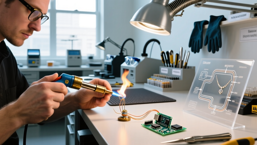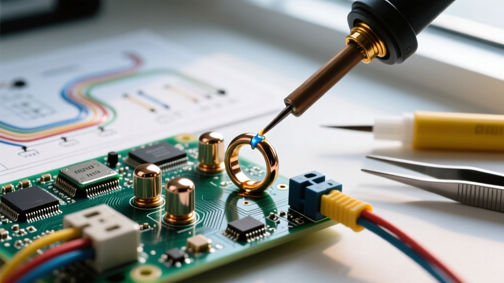

The Core Conflict: Ring Soldering vs. Mechanical Crimping
In the realm of industrial electronics, heavy machinery, and marine electrical systems, the termination of stranded wire to ring terminals is a critical point of failure. For decades, technicians have debated the merits of ring soldering versus cold mechanical crimping. While the IPC-A-620 wire harness assembly standards permit soldering under specific conditions, the broader industrial consensus heavily favors precision cold crimping for high-vibration environments. However, ring soldering remains an indispensable technique for specific applications involving potting, extreme moisture sealing, and low-frequency static loads.
Understanding when to deploy a high-wattage soldering station versus a pneumatic crimp press requires a deep dive into material science, vibration physics, and capital equipment economics. This guide dissects the technical realities of ring soldering in 2026, providing actionable frameworks for electrical engineers and master technicians.
Industry Standard Note: According to IPC-A-620, a soldered connection is acceptable provided the wire strands are visible, the solder wets the terminal properly, and critically, solder does not wick under the wire insulation to create a rigid stress point.
Failure Mode Deep Dive: The Danger of Solder Wicking
The primary argument against ring soldering in dynamic environments is the phenomenon of solder wicking (capillary action). When heat and flux are applied to a stranded copper wire inserted into a ring terminal barrel, the molten solder alloy is drawn up into the interstitial spaces between the copper strands.
The Physics of Vibration Fatigue
Stranded wire is engineered for flexibility; the individual strands slide past one another to absorb mechanical stress. When solder wicks into the wire, it binds the strands together, transforming a flexible multi-core wire into a rigid solid-core wire. The exact boundary where the flexible wire meets the rigid, solder-wicked section becomes a stress concentration point (or stress riser).
- Cyclic Loading: In automotive or industrial motor applications, vibration causes the wire to flex. The flexing is entirely concentrated at the boundary of the solder wicking.
- Work Hardening: The copper strands at this boundary undergo rapid work hardening, leading to micro-fractures.
- Catastrophic Failure: Over months of vibration, these micro-fractures propagate, resulting in a clean, brittle snap of the wire just outside the terminal barrel, often hidden beneath heat shrink tubing.
Mitigating the Wicking Effect
If ring soldering is required, technicians must employ a 'flux barrier' or mechanical stop. Applying a small dab of high-temperature silicone or using a specialized crimp-solder terminal with an integrated internal stop prevents the molten alloy from migrating past the barrel. Furthermore, using a minimal amount of Rosin Mildly Activated (RMA) flux rather than aggressive water-soluble fluxes reduces the capillary draw.
Capital Equipment & Consumables Matrix
Choosing between ring soldering and crimping is not just a technical decision; it is a capital expenditure (CapEx) calculation. Below is a comparative matrix of professional-grade setups required for high-reliability terminations (AWG 16 to 4/0) in a modern workshop.
| Parameter | Precision Cold Crimping Setup | Heavy-Duty Ring Soldering Setup |
|---|---|---|
| Primary Tool | Astro Tool 61602 Ratcheting Crimper | Metcal PS-900 Soldering Station |
| Approx. Tool Cost (2026) | $285 - $320 | $650 - $720 |
| Consumable Cost | TE Connectivity PIDG Terminals ($0.40/ea) | SAC305 Solder Wire & RMA Flux ($0.15/termination) |
| Die/Tip Requirements | Color-coded dies (Red/Blue/Yellow) | STTC-146 Chisel Tip (700°F for large lugs) |
| Cycle Time (AWG 10) | 4 - 6 seconds | 12 - 18 seconds (heat + cool) |
| Operator Skill Curve | Low (Ratchet ensures complete cycle) | High (Requires wetting & thermal management) |
| Vibration Resistance | Exceptional (Gas-tight cold weld) | Poor to Moderate (Risk of fatigue snapping) |
For high-volume production lines, the speed and repeatability of ratcheting crimp tools or pneumatic presses make crimping the undisputed champion. However, for field repairs, custom one-off harnesses, or heavily oxidized legacy wiring, a high-thermal-mass soldering station provides unmatched versatility.
When Ring Soldering is the Superior Choice
Despite the dominance of crimping, ring soldering remains the specified method in several critical industry applications where mechanical crimping falls short:
- Potting and Encapsulation: When a wire harness will be potted in epoxy or polyurethane resin, soldered ring terminals provide a completely sealed barrel. Crimped barrels can trap air or allow moisture ingress, which expands during thermal cycling and cracks the potting compound.
- Extreme Moisture Environments (Marine): While the American Boat and Yacht Council (ABYC) E-11 standards strongly advocate for crimping, field technicians often use a hybrid approach: crimping for mechanical strength, followed by ring soldering to fill the microscopic voids in the barrel, preventing saltwater crevice corrosion.
- Oxidized or Legacy Wiring: When repairing older industrial machinery where the stranded copper has suffered mild surface oxidation, a mechanical crimp may fail to bite through the copper oxide layer. The chemical cleaning action of activated flux combined with molten solder ensures a perfectly wetted, low-resistance metallurgical bond.
- High-Amperage Battery Lugs (2/0 to 4/0 AWG): For massive battery cables in forklifts or solar banks, heavy copper tube lugs are often filled with a solder slug and heated with a propane torch or heavy iron, creating a solid block of conductive material that handles 300+ amps without thermal runaway.
Standard Operating Procedure: High-Amperage Ring Soldering
Executing a defect-free soldered ring terminal on heavy-gauge wire (e.g., 2 AWG battery cables) requires strict thermal management. Using an undersized iron will result in a 'cold joint' where the solder melts against the iron tip but fails to wet the massive thermal sink of the copper lug.
Required Equipment
- High-wattage iron (Minimum 150W, e.g., Weller WSP150 or equivalent heavy-duty station).
- Lead-free SAC305 solder wire (0.062" diameter) with 2% no-clean flux core.
- Adhesive-lined dual-wall heat shrink (e.g., 3M MDT or Raychem).
- Isopropyl alcohol (99%) and lint-free wipes.
Execution Steps
- Preparation: Strip the 2 AWG wire to the exact depth of the terminal barrel plus 1/16th of an inch. Do not twist the strands tightly; maintain their natural lay.
- Pre-Shrink: Slide the adhesive-lined heat shrink onto the wire before inserting the wire into the terminal.
- Fluxing: Apply a minimal amount of RMA paste flux to the exposed copper strands and the inside of the terminal barrel.
- Thermal Transfer: Apply the pre-tinned, 700°F chisel tip directly to the terminal barrel, not the wire. The goal is to heat the terminal to the solder's liquidus temperature (approx. 428°F / 220°C for SAC305).
- Feeding the Alloy: Once the barrel is hot enough to instantly melt the solder wire on contact, feed the solder into the wire entry point. Capillary action will draw the solder through the barrel. Stop feeding when a small fillet forms at the wire entry.
- Cooling & Inspection: Remove the heat and hold the wire perfectly still for 10-15 seconds. A disturbed joint during the plastic phase will result in a fractured, high-resistance connection.
- Sealing: Slide the adhesive heat shrink over the barrel and wire insulation. Apply heat until the adhesive purges slightly from the ends, ensuring a watertight environmental seal.
Expert FAQ on Ring Terminal Assembly
Can I use standard rosin-core electronics solder for automotive ring terminals?
Technically yes, but it is highly discouraged. Standard Sn60/Pb40 or Sn63/Pb37 electronics solder lacks the mechanical shear strength required for automotive vibration. Furthermore, the flux in electronics solder is often insufficient to penetrate the heavier oxidation found on automotive-grade copper. Always use a dedicated plumbing/electrical flux or a solder alloy specifically formulated for heavy-duty terminations.
Why does my soldered ring terminal look dull and grainy?
A dull, grainy appearance is the hallmark of a disturbed joint or a cold joint. This occurs if the wire moved before the solder fully transitioned from its plastic (mushy) phase to its solid phase, or if the iron lacked the thermal mass to properly heat the heavy copper lug. The metallurgical grain structure is fractured, resulting in a brittle connection with high electrical resistance.
Is 'crimp and solder' a valid hybrid technique?
Yes, but it must be done in the correct order. You must crimp first, then solder. If you solder first, the hardened solder block prevents the crimp dies from compressing the copper strands properly, potentially damaging the crimp tool or creating a false crimp. Crimping first establishes the mechanical gas-tight bond, and subsequently wicking a small amount of solder into the barrel provides secondary environmental sealing.
Final Verdict for System Integrators
For 90% of industrial, automotive, and aerospace wiring harness applications, precision mechanical crimping using calibrated tools and TE Connectivity's terminal engineering guidelines remains the gold standard for reliability and speed. However, ring soldering is far from obsolete. When deployed strategically for potting prep, extreme environmental sealing, or heavy-amperage static battery lugs, a properly executed soldered ring terminal provides a robust, corrosion-resistant termination that outlasts the equipment it powers.