
The Thermodynamics of Soldering: Why One Temperature Doesn't Fit All
Setting the correct temperature for soldering electronics is not about picking a single, universal magic number. It is a dynamic calculation based on material compatibility, thermal mass, and flux chemistry. When you touch an iron tip to a PCB pad, heat transfers via conduction. The rate of this transfer depends on the tip geometry, the wattage of the heating element, and the thermal sink effect of the copper traces and vias connected to the pad. According to the IPC J-STD-001 requirements for soldered electrical assemblies, achieving a reliable metallurgical bond requires the solder to reach its liquidus temperature while the flux is fully activated, without exceeding the thermal degradation limits of the component or the FR-4 substrate.
Material Compatibility Matrix: Temperature for Soldering Electronics
The following matrix provides baseline temperature parameters based on the specific solder alloy and the thermal mass of the target component. These values assume a standard conical or chisel tip with adequate surface contact.
| Component / Thermal Mass | Recommended Alloy | Alloy Liquidus | Optimal Iron Tip Temp | Max Dwell Time |
|---|---|---|---|---|
| 0402 / 0603 SMD Passives (Low) | Sn63/Pb37 or Sn42/Bi57 | 183°C / 138°C | 300°C - 320°C | 1.5 - 2.0 seconds |
| SOIC / QFP ICs (Medium) | SAC305 (Lead-Free) | 217°C - 220°C | 340°C - 360°C | 2.0 - 3.0 seconds |
| TO-247 / Large Connectors (High) | SAC305 or Sn60/Pb40 | 217°C / 183°C | 370°C - 390°C | 3.0 - 5.0 seconds |
| Heavy Ground Planes (Extreme) | SAC405 with Pre-heating | 217°C - 219°C | 380°C - 400°C | 4.0 - 6.0 seconds |
Alloy Melting Points vs. Iron Tip Temperature (The Delta Rule)
A common mistake among hobbyists and junior technicians is setting the soldering station to the exact melting point of the solder alloy. If SAC305 melts at 217°C, setting the iron to 220°C will result in a catastrophic failure to solder. This is because the moment the hot tip touches the room-temperature copper pad, heat is instantly wicked away. The tip temperature will plummet below the liquidus point before the solder wire can melt.
The 150°C Delta Rule: As a general baseline, your iron tip must be set approximately 100°C to 150°C above the liquidus temperature of the solder alloy. This thermal buffer ensures the tip holds enough kinetic energy to transfer heat through the flux barrier, into the pad, and into the component lead fast enough to form a proper intermetallic compound (IMC) layer before the flux burns off.
Lead-Free (SAC305) vs. Leaded (Sn63/Pb37) Thermal Profiles
The transition to RoHS compliance forced the industry toward lead-free alloys like SAC305 (Tin 96.5%, Silver 3%, Copper 0.5%). According to data from Indium Corporation, SAC305 has a liquidus point of 217°C, compared to the eutectic 183°C of traditional Sn63/Pb37. Because SAC305 melts at a higher temperature and exhibits poorer wetting characteristics due to higher surface tension, it requires a higher tip temperature—typically 350°C to 380°C. Conversely, Sn63/Pb37 wets beautifully at lower temperatures, allowing you to run your iron at a safer 300°C to 330°C, significantly extending tip life and reducing the risk of delaminating sensitive IC packages.
Low-Temperature Bismuth Alloys (Sn42/Bi57)
For rework on heat-sensitive components or flexible PCBs, Sn42/Bi57 (melting point 138°C) is invaluable. You can set your station to a remarkably low 220°C to 250°C. However, bismuth alloys are brittle and prone to fatigue cracking under mechanical stress; they should never be used for connectors or components subject to physical vibration.
Flux Activation Temperatures: The Hidden Variable
Solder wire is not just metal; it is a delivery system for flux. The flux core must activate (boil and clean the oxidation off the copper) before the solder melts. Most rosin-based (R, RMA, RA) and no-clean fluxes activate between 150°C and 180°C. If your iron temperature is too low, the solder will melt before the flux can clean the pad, resulting in a sluggish, grainy joint that refuses to flow. If your iron is set too high (e.g., 420°C+), the flux will instantly vaporize and burn into a hard, black carbonized residue before the heat has time to penetrate the component lead, leaving you with a dry, oxidized cold joint.
Thermal Mass and Component Sensitivity: Real-World Scenarios
Understanding how to adjust the temperature for soldering electronics requires analyzing the physical geometry of your PCB.
Scenario A: 0402 SMD Capacitors on ENIG Pads
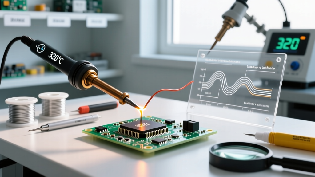
Electroless Nickel Immersion Gold (ENIG) pads offer a flat, oxidation-resistant surface but require precise thermal management. A 0402 capacitor has almost zero thermal mass. If you use a massive chisel tip at 380°C, the pad will heat instantly, potentially cracking the ceramic body of the capacitor due to thermal shock. Solution: Use a micro-conical tip (e.g., JBC C245-945) at 320°C with a fine-tipped flux pen. Apply heat for exactly 1 second.
Scenario B: Heavy Ground Planes and TO-247 Transistors
Soldering a MOSFET tab to a multi-layer ground plane is a battle against thermal dissipation. The copper plane acts as a massive heat sink, pulling energy away from the joint. If you use a low-wattage iron at 350°C, you will hold the tip in place for 15 seconds trying to melt the solder, which will eventually cook the component and lift the PCB pad. Solution: Increase the iron temperature to 390°C, use a high-thermal-mass bevel tip (e.g., Hakko T18-C4), and apply liquid flux generously. Better yet, use a PCB pre-heater set to 100°C to reduce the thermal delta the iron must overcome.
Troubleshooting Thermal Failures
When the temperature for soldering electronics is miscalibrated, the physical joint will reveal the error. Use this diagnostic guide to read your failed joints:
- Cold / Grainy Joints: The solder looks dull, lumpy, and frosty. Cause: Iron temperature too low, or dwell time too short. The solder reached a semi-solid state but never fully formed the intermetallic bond with the copper.
- Pad Lifting / Delamination: The copper pad peels away from the fiberglass substrate. Cause: Iron temperature too high combined with excessive dwell time. The FR-4 resin reaches its glass transition temperature (Tg) and loses adhesion.
- Tombstoning (SMDs): One end of a surface-mount component lifts off the pad. Cause: Asymmetric heating. One pad is connected to a ground plane (cooling it) while the other is a simple trace. The solder on the trace melts first, and the surface tension pulls the component upright.
- Charred / Blackened Flux Residue: Hard, black crust around the joint that cannot be cleaned with isopropyl alcohol. Cause: Tip temperature exceeding 400°C, instantly burning the rosin activators.
Expert Soldering Station Recommendations for Thermal Control
Maintaining the correct temperature under load requires a station with aggressive thermal recovery. The NASA Workmanship Standards emphasize the necessity of closed-loop temperature control in high-reliability soldering.
1. JBC CD-2BQE (Advanced Active Thermal Management)
Price Range: $600 - $650
JBC stations utilize cartridges where the heating element and tip are integrated. This allows the C245 tips to heat from room temperature to 350°C in under 2 seconds. Because the thermal recovery is instantaneous, you can set a JBC station 30°C to 40°C lower than a traditional station to achieve the exact same soldering result, drastically reducing thermal stress on sensitive ICs.
2. Hakko FX-951 (Industry Standard Workhorse)
Price Range: $330 - $360
Using the T18 tip series, the FX-951 features a 70W ceramic heater with excellent thermal feedback. It is the gold standard for mid-volume production and advanced hobbyists. For heavy ground planes, upgrading to the Hakko FX-838 (150W) ensures the tip temperature doesn't collapse when touching massive copper pours.
3. Weller WE1010NA (Budget Precision)
Price Range: $110 - $130
For those strictly soldering leaded through-hole components and basic SMDs, the 70W Weller WE1010NA provides reliable digital temperature control. Pair it with the ETA chisel tip for Sn63/Pb37 work at 320°C for an unbeatable budget setup.
Final Thoughts on Material Compatibility
Mastering the temperature for soldering electronics is an exercise in material science. By matching your solder alloy's liquidus point, your flux's activation threshold, and your component's thermal mass to the correct iron profile, you eliminate guesswork. Invest in a high-recovery station, respect the delta rule, and let the metallurgy do the work.