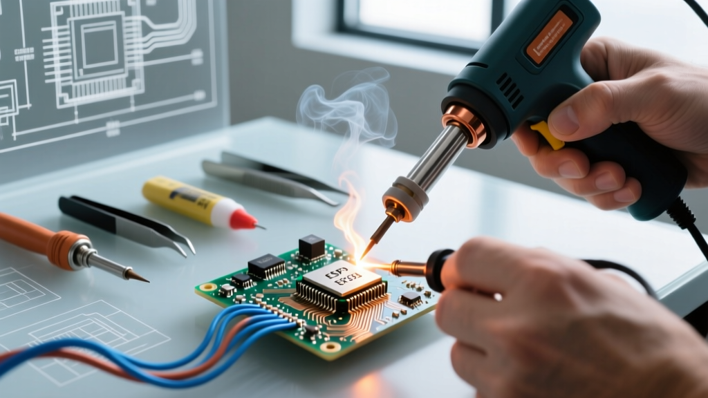

Every electronics hobbyist eventually faces a moment of desperation: a broken soldering iron, an unusually massive ground plane that sucks the heat out of a 60W iron, or a sudden need to terminate a heat-shrink solder sleeve in the field. The temptation to grab a standard hardware store heat gun is high. But soldering with a heat gun—specifically a high-airflow, imprecise thermal tool meant for paint stripping or shrink tubing—is a notorious pathway to destroyed PCBs, oxidized pads, and unreliable connections.
This comprehensive FAQ and troubleshooting guide breaks down the physics of why standard heat guns fail at precision soldering, how to salvage a board if you have already attempted it, and the specific edge cases where broad-spectrum hot air is actually the correct tool for the job.
The Core Distinction: Hardware Heat Guns vs. Hot Air Rework Stations
Before troubleshooting, we must establish a critical hardware distinction that causes 90% of beginner failures. According to IPC standards for hand soldering (IPC-J-STD-001), thermal control and airflow direction are paramount to preventing thermal damage to components and laminate substrates.
- Standard Heat Guns (e.g., Wagner HT1000, Milwaukee M18): Output 500°F to 1,000°F+ with massive, unfocused airflow (often 15–20 CFM). They are designed to blanket large surface areas. Using these for PCB soldering will blow 0402 SMD components across the room and delaminate FR4 fiberglass.
- Hot Air Rework Stations (e.g., Quick 861DW, Hakko FR-810B): Output precisely regulated heat (100°C–480°C) with low, focused airflow (2–10 liters per minute) via interchangeable nozzles. These are designed for SMD reflow and desoldering.
Troubleshooting Matrix: Diagnosing Heat Gun Soldering Failures
If you have already attempted soldering with a standard heat gun and are experiencing connection failures, use this diagnostic matrix to identify the root cause and apply the correct rework procedure.
| Failure Mode | Visual Symptom | Root Cause (Heat Gun Specific) | Corrective Action |
|---|---|---|---|
| Severe Oxidation | Solder forms dull, grey, crumbly balls; refuses to wet the pad. | High-volume airflow introduces excess oxygen at 700°F+, instantly oxidizing flux and copper before reflow occurs. | Remove oxidized solder with desoldering braid. Scrub pad with fiberglass pen. Apply fresh tack flux (e.g., Amtech NC-559) and reflow with a proper iron. |
| Pad Delamination | Copper pad lifts off the PCB, taking the fiberglass substrate with it. | Dwell time exceeded 45 seconds. Standard FR4 has a Glass Transition Temperature (Tg) of ~130°C–140°C; prolonged heat gun exposure breaks the epoxy bond. | Pad is destroyed. Must scrape solder mask off the connected trace and solder a 30 AWG kynar wire jumper directly to the via or trace. |
| Component Tombstoning | One side of an SMD capacitor/resistor lifts vertically off the pad. | Uneven heating. The broad airflow heated one pad faster than the other, causing asymmetric surface tension pull during reflow. | Hold component flat with ceramic tweezers. Apply flux to both pads. Use a fine-tip iron (e.g., Hakko FX-951 with a 0.8mm conical tip) to simultaneously heat both pads. |
| Insulation Melt-Back | Wire insulation shrinks, melts, or chars inches away from the joint. | Lack of thermal...Related guides |