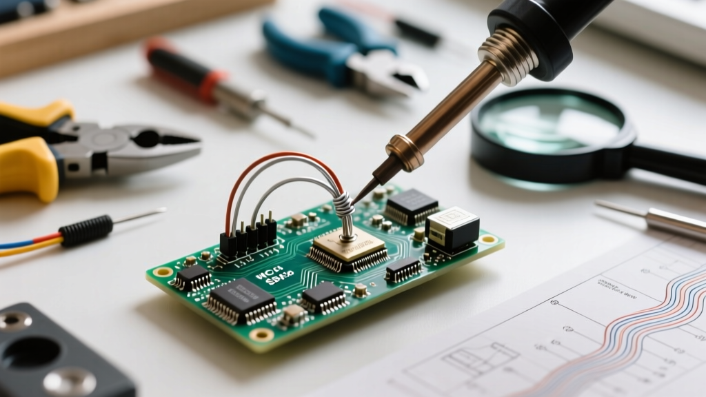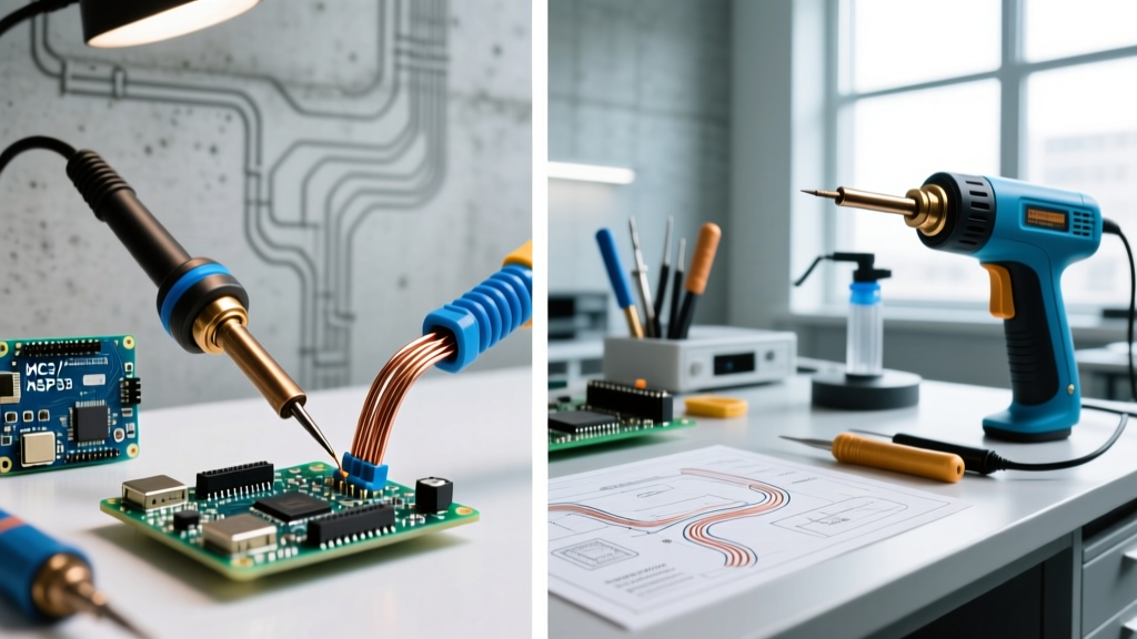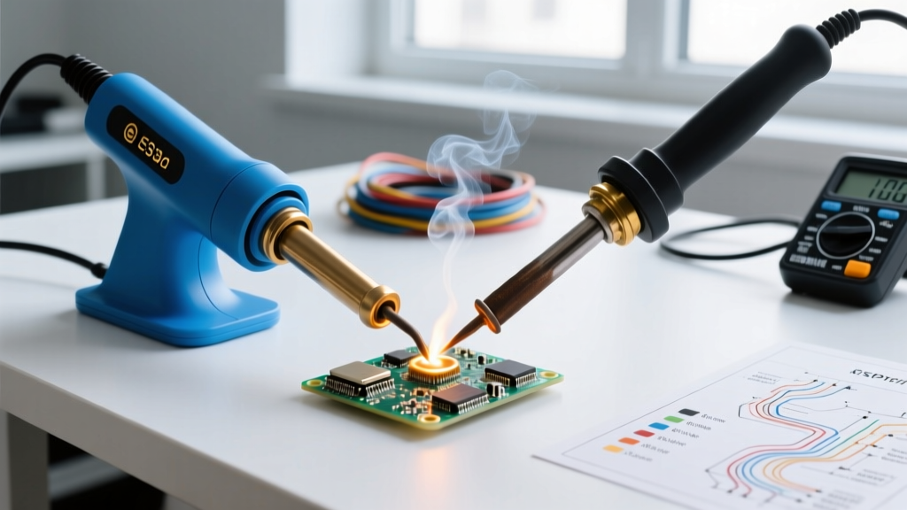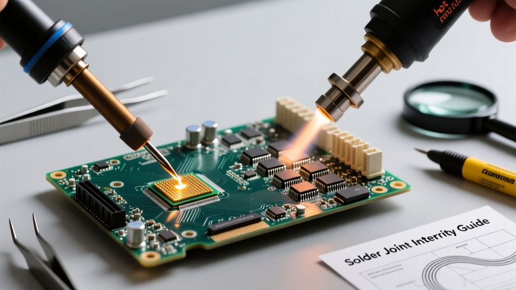

Introduction to Industrial Desoldering Standards
In high-reliability electronics manufacturing and repair—spanning aerospace, medical devices, and automotive ECUs—component removal is a high-stakes operation. While automated desoldering stations and vacuum tweezers have their place, mastering how to use soldering wick (also known as desoldering braid) remains an indispensable skill for rework technicians. When dealing with fine-pitch surface-mount devices (SMDs), QFNs, or BGAs, solder wick provides unparalleled capillary action to clear solder from pads without the mechanical stress associated with vacuum pumps or solder suckers.
According to the IPC-7711/7721 standard for rework and repair of electronic assemblies, the goal of desoldering is to remove components and solder without damaging the printed circuit board (PCB) laminate, lifting copper pads, or compromising the integrity of nearby vias. Soldering wick, when paired with the correct thermal profile and flux chemistry, is the industry-preferred method for achieving IPC-compliant pad preparation.
Selecting the Right Braid Width and Flux Chemistry
Industrial soldering wick is not a one-size-fits-all consumable. It is manufactured from high-purity, oxygen-free copper woven into precise geometric patterns and pre-coated with specific flux chemistries. Choosing the wrong width or flux type is the leading cause of rework failure in professional environments.
Braid Width Sizing Matrix
The width of the wick must match the footprint of the solder joint. Using a wick that is too wide will draw heat away from the target pad, increasing dwell time and the risk of thermal damage. Using a wick that is too narrow will require multiple passes, similarly increasing thermal exposure.
- #1 (1.0mm / 0.039"): Ideal for 0402, 0603, and fine-pitch (0.5mm) QFPs.
- #2 (1.5mm / 0.060"): Standard for 0805, 1206, and SOIC packages.
- #3 (2.0mm / 0.075"): Used for DIP through-hole components and larger SMDs.
- #4 (2.5mm+ / 0.100"): Reserved for heavy ground planes, large power lugs, and TO-220 tabs.
Flux Chemistry Selection for Industry Applications
The flux coating on premium wicks (such as those from Chemtronics Soder-Wick or Kester) lowers the surface tension of the molten solder, enabling rapid capillary flow. Below is a comparison matrix to guide procurement based on your industry's cleaning protocols.
| Flux Type | Residue Profile | Cleaning Required? | Primary Industry Application |
|---|---|---|---|
| Rosin (RMA) | Amber, sticky, non-conductive | Optional (but recommended for aesthetics) | General consumer electronics, hobbyist, standard commercial repair. |
| No-Clean | Clear, <0.5% solid residue | No (leaves safe, non-corrosive residue) | Medical devices, telecommunications, high-density SMT where washing is impossible. |
| Water-Soluble (OA) | Highly active, corrosive if left | Yes (Mandatory DI water wash) | Aerospace, automotive, and high-reliability military boards requiring pristine ionic cleanliness. |
Step-by-Step: How to Use Soldering Wick on Fine-Pitch ICs
Executing a flawless desoldering operation requires strict adherence to thermal management and mechanical technique. The following procedure outlines how to use soldering wick for removing a 0.65mm pitch TSSOP (Thin Shrink Small Outline Package) integrated circuit.
- Pre-Heat and Shield: Apply polyimide (Kapton) tape around the target IC to protect adjacent components from accidental solder bridges and thermal exposure. If available, use a PCB pre-heater set to 100°C to reduce the thermal delta the soldering iron must overcome.
- Iron and Tip Selection: Use a high-wattage soldering station (minimum 60W, preferably 80W-120W) to ensure rapid thermal recovery. Fit a bevel tip (e.g., Hakko T18-C3 or Weller RT4) rather than a fine point. The bevel increases the contact area between the iron, the wick, and the pad.
- Set the Temperature Profile: For lead-free solder (SAC305), set the station to 360°C - 380°C. For legacy tin-lead (Sn63/Pb37) assemblies, 320°C - 340°C is sufficient.
- Apply Fresh Flux: Even though the wick is pre-fluxed, applying a small amount of high-quality tacky flux (e.g., Amtech NC-559) directly to the IC pins ensures maximum wetting and prevents the wick from sticking to the pads.
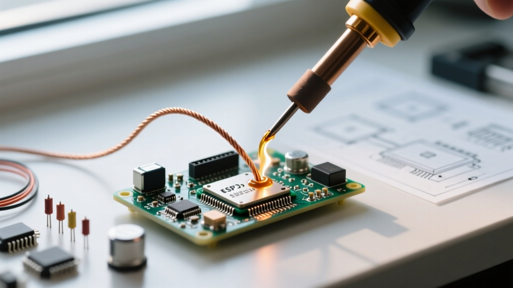
- The Placement and Heat Transfer Sequence: Place the unspooled wick directly over the target pins. Do not heat the wick in the air. Place the soldering iron tip directly on top of the wick, pressing down gently. The iron heats the wick, and the wick heats the pad simultaneously.
- Observe Capillary Action: Within 1 to 2 seconds, the solder will melt and wick upward into the copper braid. The wick will change color from copper to silver. Slowly drag the iron and wick together along the row of pins at a speed of roughly 1cm per second.
- Cut and Repeat: Once the wick is saturated (silver), snip off the used portion with flush cutters. Never attempt to reuse saturated wick; its capillary capacity is exhausted.
- Final Pad Cleanup: For BGA or QFN pads requiring absolute flatness, perform a final, ultra-light pass with a fresh #1 wick and minimal pressure to ensure no microscopic solder domes remain.
Mitigating Thermal Damage and Pad Lifting
The most catastrophic failure mode when learning how to use soldering wick is pad delamination (lifting). Copper pads are bonded to the FR-4 fiberglass substrate using epoxy resins that degrade rapidly at temperatures exceeding 260°C. While your iron is set to 360°C, the actual temperature at the pad interface should not exceed the solder's liquidus point for more than a few seconds.
The 3-Second Dwell Rule
Industry Rule of Thumb: Never allow the soldering iron to dwell on a single pad or via for more than 3 to 5 seconds. If the solder does not flow into the wick within 3 seconds, remove the iron, allow the board to cool for 10 seconds, apply more liquid flux, and try again with a slightly higher iron temperature or a wider tip.
Forcing the wick by applying heavy downward pressure is a common novice mistake. Excessive pressure crushes the microscopic vias beneath the pads and acts as a mechanical wedge that can peel the copper trace off the laminate. The iron should rest on the wick with only the weight of the handpiece providing the contact force.
Dealing with Stubborn Ground Planes
When desoldering components attached to large internal ground planes, the PCB acts as a massive heatsink, pulling heat away from the joint. In these scenarios, standard wick fails because the solder never reaches its liquidus state. To resolve this without turning your iron up to a destructive 420°C:
- Utilize a localized hot air pencil set to 250°C to pre-heat the specific ground plane area.
- Switch to a #4 (2.5mm) or #5 (3.5mm) heavy-duty wick which possesses greater thermal mass.
- Use a soldering iron with a heavy thermal storage tip (e.g., a chisel tip with a 4mm+ diameter shaft).
Procurement and Cost Analysis for Production Environments
In a high-volume rework or manufacturing environment, procurement strategies for soldering wick shift from convenience to cost-efficiency and quality control. Standard 5-foot (1.5m) spools of premium No-Clean wick typically retail between $6.00 and $9.00 per spool. While acceptable for low-volume repair benches, this format generates excessive plastic waste and requires frequent spool changes.
For production environments, purchasing industrial 50-foot or 100-foot continuous rolls is standard practice. A 50-foot roll of Chemtronics Soder-Wick (No-Clean, #2 width) costs approximately $45.00 to $55.00, reducing the cost per foot by nearly 40%. Furthermore, continuous rolls can be loaded into automated wick-dispensing handpieces, which keep the unused braid sealed from ambient humidity. Moisture absorption is a silent killer of desoldering braid; oxidized copper will not wick solder, and moisture trapped in the flux can cause microscopic splattering (solder balls) that lead to latent short circuits.
Frequently Asked Questions
Can I use rubbing alcohol to clean the board after using No-Clean wick?
Yes, but it is generally unnecessary. No-Clean flux residues are designed to be benign and non-conductive. If aesthetics or subsequent conformal coating adhesion require cleaning, use a dedicated PCB cleaner or high-purity isopropyl alcohol (IPA 99%) with a lint-free swab. Avoid standard rubbing alcohol (70% IPA), as the 30% water content can trap ionic contaminants under components.
Why is my soldering wick sticking to the PCB pads?
Wick sticks to pads when the flux has completely burned off, leaving raw copper to alloy with the pad's surface finish. This happens if you dwell too long or if the wick was left exposed to air and oxidized prior to use. If the wick sticks, do not pull it, as you will rip the pad off the board. Instead, apply fresh liquid flux directly to the stuck area, re-heat with the iron until the solder reflows, and gently slide the wick away.
Is solder wick better than a desoldering pump for through-hole components?
For bulk removal of through-hole solder, a high-quality pneumatic desoldering gun (like the Hakko FR-410) is faster and more efficient. However, solder wick is vastly superior for the final cleanup of the plated through-hole (PTH) barrel. Pumps often leave a thin ring of solder inside the barrel, which can prevent component insertion or cause hidden cold joints. A quick pass with #3 wick ensures a perfectly clear, IPC-compliant via.