
The Physics of Termination: Gas-Tight Seals vs. Intermetallic Bonds
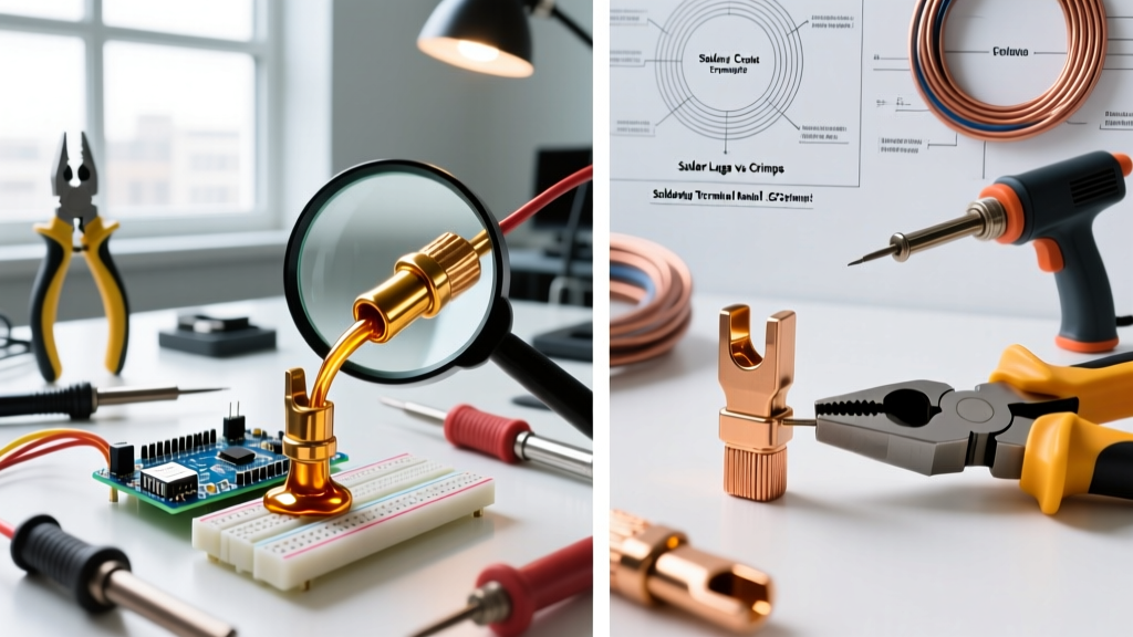
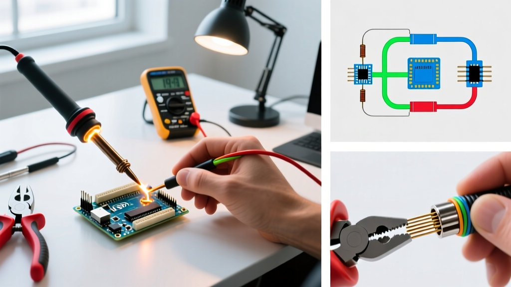
The debate between crimping vs soldering remains one of the most contested topics in electrical engineering, EV conversions, and aerospace wiring. To troubleshoot failures effectively, you must first understand the underlying physics of each method. Soldering relies on an intermetallic compound (IMC) layer formed when molten alloy (like SAC305 or Sn63Pb37) wets the copper strands. Crimping, conversely, relies on extreme mechanical deformation to create a gas-tight seal, cold-welding the terminal and wire strands together by breaking through surface oxides without heat.
While both methods can create reliable connections, their failure modes are entirely different. In 2026, with the rise of high-vibration robotics and high-current EV architectures, understanding how to diagnose and prevent these specific failures is critical for system reliability.
Troubleshooting Soldered Connections: Common Failures
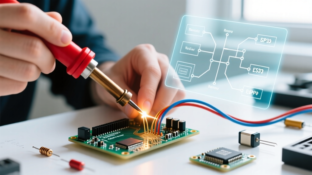
Solder joints are highly sensitive to thermal profiles and mechanical stress. Here is how to diagnose the most frequent soldering failures.
1. Cold Solder Joints and Grainy Fractures
Symptoms: The joint looks dull, gray, or lumpy rather than smooth and shiny (for leaded) or smooth and matte (for lead-free). The connection exhibits high resistance or intermittent continuity.
Root Cause: Insufficient heat transfer. The iron tip heated the solder, but not the copper wire and pad, preventing proper wetting and IMC formation. This is common when using undersized irons (e.g., a 40W iron on 10 AWG wire) or failing to use adequate flux.
The Fix: Increase thermal mass. Use a high-capacity station like the Hakko FX-951 or Pinecil V2 with a heavy chisel tip (e.g., Hakko T12-D24). Apply external no-clean or rosin flux (like Amtech NC-559) before heating. Heat the wire and terminal simultaneously for 2-3 seconds before feeding the solder.
2. Solder Wicking and Vibration Fatigue
Symptoms: The wire breaks cleanly at the exact edge of the solder joint after weeks of use in a vibrating environment (e.g., drones, automotive harnesses).
Root Cause: Capillary action pulls molten solder under the wire insulation. This creates a rigid section of wire right next to a flexible section. Under vibration, the mechanical stress concentrates at this stiff-to-flexible transition point, leading to copper fatigue and fracture.
The Fix: Never solder under the insulation. Strip the wire precisely so that a 1mm gap remains between the insulation and the start of the solder joint. For high-vibration environments, abandon soldering entirely and switch to crimping.
Troubleshooting Crimped Terminations: Common Failures
Crimping is often perceived as foolproof, but a bad crimp is arguably more dangerous than a bad solder joint because it can fail catastrophically under high current without visual warning signs.
1. Wire Pull-Out and Low Pull Force
Symptoms: The wire slides out of the terminal with minimal force (fails the IPC pull-test requirement of ~15-30 lbs depending on gauge).
Root Cause: Using the wrong wire type for the terminal. A massive troubleshooting trap in 2026 is the use of silicone-stranded wire. Silicone wire has a much smaller copper core diameter than PVC wire of the exact same AWG rating due to thinner individual strands. If you crimp 18 AWG silicone wire into a standard 22-16 AWG PVC-rated terminal, the crimp will be too loose.
The Fix: Match terminals to the wire's cross-sectional area (mm²), not just the AWG label. Alternatively, use a ratcheting crimper with adjustable die pressure, or fold the silicone wire back on itself before inserting it into the barrel to increase copper density.
2. Insulation Crimp Crushing and Bellmouth Failures
Symptoms: The wire insulation is cut or severely deformed by the metal crimp tabs, or the wire strands are sheared off flush with the front of the terminal.
Root Cause: Improper wire strip length and terminal placement in the die. According to the NASA-STD-8739.4 Crimping Standard, a proper crimp must feature a "rear bellmouth" (0.5mm to 1.0mm of exposed copper between the insulation crimp and conductor crimp) to prevent the insulation tabs from cutting into the current-carrying strands.
The Fix: Adjust your strip length. Ensure the wire is seated fully into the terminal barrel before squeezing the ratcheting tool. Use precision tools like the Engineer PA-09 for micro-connectors or TE Connectivity CERTI-CRIMP dies for production-grade automotive terminals to guarantee correct bellmouth formation.
Crimping vs Soldering: Technical Comparison Matrix
| Feature | Soldering | Crimping |
|---|---|---|
| Connection Physics | Intermetallic Alloy Bond | Gas-Tight Cold Weld |
| Vibration Resistance | Poor (Prone to fatigue cracking) | Excellent (Strands flex together) |
| Current Capacity | Limited by solder alloy melting point | Limited by copper terminal mass |
| Tooling Cost (Entry) | $25 - $60 (Pinecil, basic iron) | $30 - $50 (Engineer PA-09, IWISS) |
| Tooling Cost (Pro) | $250 - $400 (JBC, Hakko FX-951) | $300 - $800+ (TE, Molex ratcheting) |
| Inspection Method | Visual (Wetting, fillet shape) | Visual (Bellmouth) + Pull Test |
Frequently Asked Questions (FAQ)
Can I solder over a crimped connection for extra security?
No. This is a common and dangerous DIY mistake. The IPC/WHMA-A-620 Standard explicitly forbids soldering crimped connections in aerospace and high-reliability applications. Soldering a crimp fills the microscopic gaps between the cold-welded strands with a low-melting-point alloy. If the joint heats up under high current, the solder melts, the mechanical crimp expands slightly due to thermal expansion, and the connection instantly fails. Rely on a properly executed mechanical crimp instead.
Why does the aerospace industry prefer crimping over soldering?
Aerospace and military applications (governed by standards like MIL-DTL-22520) mandate crimping because of verifiability and vibration resistance. A crimp can be verified non-destructively using pin gauges to check the die compression, and destructively via calibrated pull-tests. Furthermore, aircraft experience extreme thermal cycling and high-frequency vibration; solder joints are brittle and will inevitably develop micro-fractures under these conditions, whereas a gas-tight crimp moves as a single, flexible unit with the wire.
What is the best tool for crimping small JST and Dupont connectors?
For DIY electronics, 3D printers, and custom PCB harnesses using JST-PH, XH, or Dupont 2.54mm connectors, the Engineer PA-09 (approx. $25) is the industry darling. It features precision-machined Japanese steel dies that form the correct trapezoidal crimp on the conductor and a tight fold on the insulation. For higher volume or Molex PicoClasp terminals, step up to a dedicated ratcheting crimper like the Molex 63811-1000 series to ensure consistent, repeatable gas-tight seals without hand fatigue.
How do I fix a crimp where the wire strands are cut off?
If the copper strands are sheared flush with the front of the terminal barrel, you have zero front bellmouth, meaning the terminal's sharp edges will eventually saw through the wire under thermal expansion. You cannot fix this; the terminal and wire end are ruined. Cut off the terminal, strip the wire again (leaving 1mm more copper exposed), and crimp a fresh terminal. Always verify that the wire strands protrude slightly (about 0.5mm) past the front of the conductor barrel before squeezing the tool.
Expert Verdict: Choosing the Right Termination
When deciding between crimping vs soldering, let the environment dictate the method. Use soldering for rigid, low-vibration environments like PCBs, static sensor nodes, and breadboard prototypes where thermal profiles are controlled. Use crimping for any wire-to-wire or wire-to-board connection that will experience movement, vibration, thermal cycling, or high current (such as automotive harnesses, drone ESCs, and solar panel arrays). Investing in a high-quality ratcheting crimper will yield far more reliable, inspectable, and robust connections in the field than a soldering iron ever could.