
The Role of XT60 Connectors in High-Current Industrial Applications
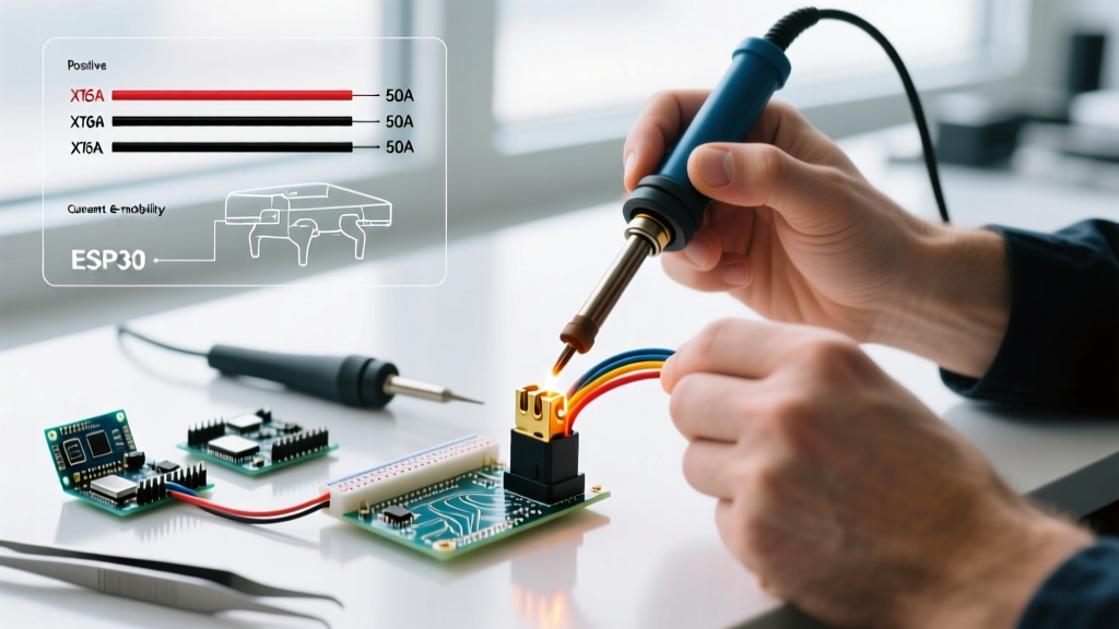
In the rapidly expanding sectors of commercial agriculture drones, autonomous delivery robotics, and light e-mobility, power distribution reliability is non-negotiable. While hobbyists often treat connectors as an afterthought, industrial engineers recognize that soldering XT60 plugs correctly is a critical point of failure in high-current DC systems. Originally designed for RC aircraft, the XT60 connector—manufactured primarily by Amass—has become an industry-standard interface for 60A continuous current applications due to its low contact resistance and robust mechanical retention.
However, industrial environments demand higher reliability than hobbyist setups. A poorly soldered XT60 joint in a 2026 commercial drone payload can lead to voltage drops, thermal runaway, or mid-flight power loss. According to OSHA guidelines on lithium-ion battery safety, poor electrical connections are a primary catalyst for localized heating and subsequent battery fires. Therefore, production-line soldering of XT60 connectors requires strict adherence to thermal management, material selection, and quality control protocols.
Material Selection: Standard XT60 vs. Amass XT60H
Before the soldering iron touches the bench, procurement and engineering teams must specify the correct connector variant. The standard yellow XT60 utilizes a PA66 (Polyamide 66) nylon housing. While durable, PA66 has a relatively low thermal deflection temperature. When subjected to prolonged soldering heat (above 350°C for more than 3 seconds), the internal brass housing can shift, compromising the mechanical grip on the male bullet connector.
For industrial manufacturing, engineers should specify the Amass XT60H (High-Temperature) variant. As noted in the official Amass connector specifications, the XT60H utilizes a specialized high-temp nylon composite that withstands soldering temperatures up to 420°C without housing deformation. This wider thermal window is crucial when soldering heavy 10 AWG silicone wires that act as massive heat sinks, requiring longer dwell times to achieve proper wetting.
Production-Grade Tooling and Soldering Stations
Soldering 10 AWG or 12 AWG stranded silicone wire to an XT60 plug requires a soldering station capable of rapid thermal recovery. Standard 40W to 60W hobbyist irons will suffer from severe thermal droop when touching the heavy brass mass of the XT60, resulting in cold, brittle joints. Industrial workstations must utilize high-wattage, active-tip technology.
| Station Model | Wattage | Thermal Recovery | Approx. Cost | Best Use Case |
|---|---|---|---|---|
| JBC CD-2BQE (C245 handles) | 130W | Instantaneous (<2s) | $620 - $680 | High-volume drone manufacturing |
| Hakko FX-951-66 | 70W | Fast (Active tip) | $240 - $280 | E-bike battery pack assembly |
| Weller WE1010NA | 70W | Moderate | $130 - $160 | Low-volume solar/robotics prototyping |
Solder Alloy and Flux Specifications
For industrial applications not strictly bound by RoHS (Restriction of Hazardous Substances) directives, Sn63/Pb37 (63% Tin / 37% Lead) eutectic solder remains the gold standard. It melts sharply at 183°C, reducing the time the XT60 housing is exposed to heat. If RoHS compliance is mandatory for European e-mobility exports, SAC305 (Sn96.5/Ag3.0/Cu0.5) must be used. SAC305 melts at 217°C–220°C and requires higher iron temperatures (380°C–400°C), making the XT60H housing mandatory.
Always use a high-quality no-clean or rosin-activated flux. Amtech NC-559-V2-TF tacky flux or MG Chemicals 8341 liquid no-clean flux are industry staples that break down heavy oxidation on brass contacts without leaving corrosive residues.
Step-by-Step XT60 Soldering Protocol for High-Reliability Joints
To meet the rigorous workmanship requirements outlined in IPC J-STD-001 (Requirements for Soldered Electrical and Electronic Assemblies), technicians must follow a precise, repeatable sequence. Deviating from these timings and measurements is the leading cause of field failures.
- Wire Preparation: Strip exactly 6.5mm to 7.0mm of insulation from the 10 AWG or 12 AWG silicone wire. Do not nick the copper strands. Twist the strands tightly to prevent fraying.
- Pre-Tinning the Wire: Apply a small amount of flux to the bare copper. Using a chisel tip (e.g., JBC C245-945) set to 360°C, feed Sn63/Pb37 solder into the wire strands until the wicking stops exactly at the edge of the silicone insulation. Do not allow solder to wick under the insulation.
- Pre-Tinning the XT60 Connector: Secure the XT60 plug in a specialized silicone or brass third-hand jig. Apply flux inside the brass cup. Touch the iron to the outside of the brass cup and feed solder until the cup is exactly 50% full. Avoid overfilling, which will cause the wire to bottom out and create a weak mechanical joint.
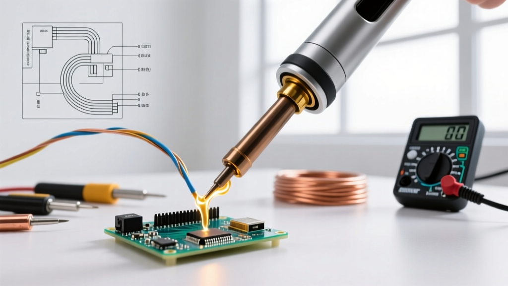
- Final Mating: Hold the pre-tinned wire parallel to the connector cup. Apply the iron to the side of the brass cup to reflow the solder pool. Insert the wire into the molten pool. Hold perfectly still for 3 to 4 seconds until the solder transitions from a shiny liquid to a solid, dull/matte finish (for leaded) or shiny solid (for lead-free).
- Cooling and Inspection: Allow the joint to cool naturally. Do not blow on it or use compressed air, as rapid cooling induces micro-fractures in the solder crystalline structure.
Production Line Pro-Tip: Always solder the negative (black) wire to the XT60 connector first, and use the male connector as a heat sink alignment tool. Inserting a male XT60 bullet into the female housing during soldering ensures the internal brass contacts remain perfectly aligned and prevents the plastic housing from warping inward due to asymmetric heat distribution.
Common Failure Modes in XT60 Solder Joints
Quality assurance teams must train optical inspection systems and manual inspectors to look for specific failure modes unique to heavy-gauge XT60 soldering.
1. The 'Cold' or Disturbed Joint
Caused by insufficient thermal mass or movement during the cooling phase. A cold joint on a 60A DC line will exhibit high electrical resistance. Under load, this resistance generates localized heat (I²R losses), eventually melting the solder and causing an arc flash. Visually, leaded cold joints appear grainy, dull, and lumpy rather than smooth and concave.
2. Insulation Wicking and Burn-Back
If the soldering iron dwells on the wire for more than 5 seconds, heat travels up the copper strands via conduction. This melts the silicone insulation, causing it to shrink back and expose bare copper near the joint. In high-vibration drone environments, this exposed, un-supported copper strand becomes a fatigue point, eventually snapping under mechanical stress.
3. Solder Starvation (Insufficient Fill)
The solder should form a smooth, concave fillet visible at the top of the brass cup, completely encapsulating the wire. If the cup is only filled at the bottom, the wire relies solely on a small surface-area bond, which will fail under the physical strain of thick 10 AWG wire being bent during battery installation.
Quality Control and IPC-A-610 Acceptability
In industrial manufacturing, soldering XT60 plugs is not a 'good enough' process; it is a measured science. Facilities producing e-mobility battery packs and commercial UAVs should align their visual inspection criteria with the IPC-A-610 standard for Class 2 (Dedicated Service Electronic Products) or Class 3 (High-Performance Electronic Products). Class 3 requires that the solder wetting is complete, the fillet is smooth and continuous, and the wire strands are fully encapsulated without any visible copper or flux char. Implementing automated optical inspection (AOI) or strict manual magnification checks ensures that every XT60 connection leaving the facility can handle 60A continuous current without thermal degradation.
Frequently Asked Questions (FAQ)
Can I use a heat gun instead of a soldering iron for XT60 plugs?
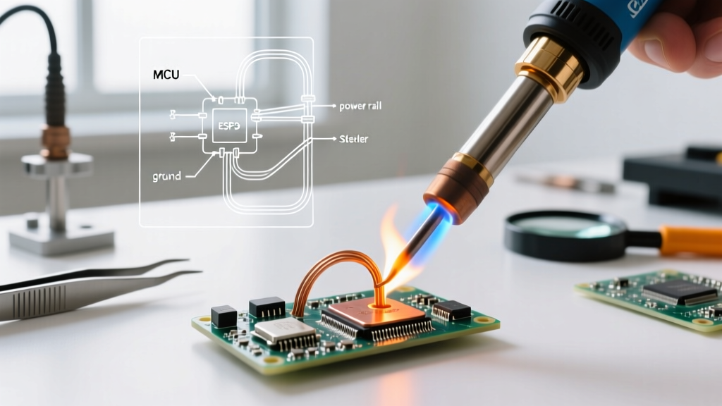
No. Heat guns cannot provide the localized, high-density thermal transfer required to melt solder inside a heavy brass cup without simultaneously melting the surrounding nylon housing and damaging the wire insulation. A high-wattage soldering station with a heavy chisel tip is mandatory.
Should I use heat shrink tubing on XT60 solder joints?
Yes, but with a caveat. Standard XT60 connectors are designed to have the heat shrink tubing cover the solder cup and overlap slightly onto the yellow/black nylon housing to provide strain relief. However, do not apply the heat shrink until after the joint has passed visual inspection. Use 3:1 ratio adhesive-lined (dual-wall) heat shrink for industrial applications to ensure a waterproof, vibration-resistant seal.
Is it safe to solder XT60 connectors directly to LiPo battery tabs?
It is highly discouraged in industrial settings. The heat transferred through the copper wire can easily reach the battery's internal safety circuits or degrade the cell chemistry. Always use a spot-welder for battery tab connections, and solder the XT60 connectors to the opposite end of the harness, keeping the heat source at least 150mm away from the battery cells.