
The Micro-Wire Thermal Paradox
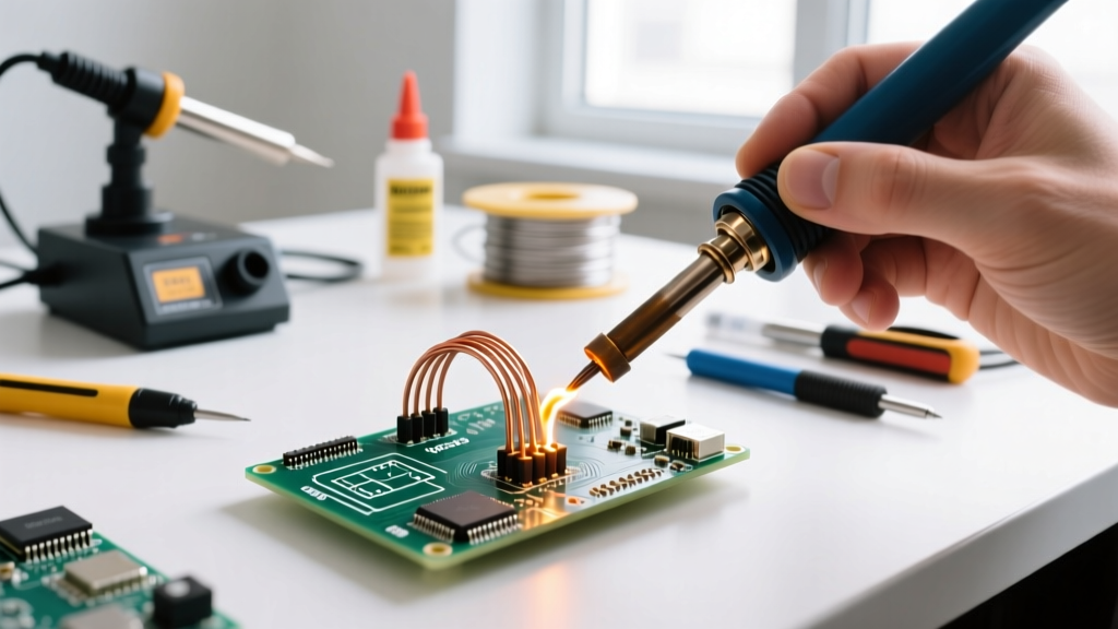
Working with small wires—specifically 24 AWG down to 32 AWG—introduces a unique thermal paradox. Because the copper cross-section is so minute (a 30 AWG wire has a diameter of just 0.010 inches), its thermal mass is nearly zero. When you apply a soldering iron, the heat wicks down the wire almost instantly. This rapid thermal transfer creates two primary failure modes: insulation shrinkback (where the jacket melts and recedes) and capillary wicking (where solder creeps under the insulation, creating a rigid stress point that snaps under vibration). In 2026, as drones, FPV systems, and miniaturized medical electronics continue to shrink, mastering the decision framework for soldering small wires is no longer optional—it is a baseline requirement for reliability.
Decision Matrix: Soldering vs. Micro-Crimping vs. Welding
Before picking up an iron, you must evaluate whether soldering is actually the correct termination method for your specific application. High-vibration environments often favor mechanical connections. Use the framework below to choose your approach.
| Method | Best Application | Estimated 2026 Cost | Reliability & Vibration | Learning Curve |
|---|---|---|---|---|
| Soldering | PCB pigtails, static wire harnesses, RC hobby electronics | $60 - $500 (Tooling) | High (Static), Low (High-Vibe) | Moderate |
| Micro-Crimping | Aerospace, automotive, high-vibration drone arms | $150 - $800 (Precision Crimpers) | Excellent (Mechanical Grip) | High (Requires exact die matching) |
| Resistance Welding | Thermocouples, battery tabs, extreme miniaturization | $2,000+ (Spot Welders) | Exceptional (Metallurgical Bond) | Very High |
For the vast majority of DIY, prototyping, and commercial static harnesses, soldering remains the most accessible and cost-effective choice. However, if your wires will experience constant harmonic vibration (like on a multirotor motor mount), consult TE Connectivity's interconnect guidelines, which heavily favor crimping for dynamic mechanical stress.
The Tooling Framework for Sub-26 AWG
Standard 60W chisel-tip irons are useless for 30 AWG wire. You need rapid thermal recovery and micro-precision tips. Here is how to select your hardware based on your budget and volume.
Tier 1: Professional & Aerospace (The JBC Ecosystem)
For production environments or mission-critical aerospace harnesses, the JBC CD-2BQE station paired with the C115-101 spoon tip is the undisputed king. The C115 series integrates the heater directly into the tip, achieving 350°C in under 2 seconds. This allows you to touch the wire, flow the solder, and remove the iron in less than 1.5 seconds, completely eliminating insulation melt. Expect to invest around $450 for the station and $75 per replacement tip.
Tier 2: Advanced Hobbyist & FPV (The Pinecil V2)
For FPV drone builders and advanced hobbyists, the Pine64 Pinecil V2 running IronOS is the optimal 2026 choice. Powered via USB-C PD at 65W, it drives the TS-B2 (0.5mm conical) or TS-I (micro knife) tips brilliantly. At roughly $26 for the iron and $5 per tip, it offers 90% of the performance of a $400 Hakko FX-951 setup, making it the ultimate framework choice for soldering 24-28 AWG silicone wires.
Precision Stripping: The Unsung Hero
You cannot solder small wires cleanly if you nick the copper strands during stripping. A single nicked strand on a 32 AWG wire reduces its tensile strength by up to 40%. Ditch the manual pliers and invest in a StripMeister Original (approx. $85) or the Ideal Industries Micro-Strip 45-181. These mechanical strippers use precision-machined blades that cut the insulation to the exact micron without scoring the copper.
Consumables: Alloy, Diameter, and Flux Chemistry
The physical dimensions of your solder wire and the chemistry of your flux dictate the success of micro-connections.
Solder Diameter Selection
- 0.015 inch (0.38mm): Mandatory for 28-32 AWG. Allows precise deposition of tiny solder volumes. (Recommended: Kester 245 63/37)
- 0.020 inch (0.50mm): Ideal for 24-26 AWG. Provides enough volume for a solid fillet without flooding the joint. (Recommended: Alpha Assembly OM328)
- 0.031 inch (0.80mm) and above: Avoid entirely for small wires. You will inevitably apply too much solder, causing bridging and excessive thermal dwell time.
Flux Chemistry
For micro-wires, flux is more important than the iron. Liquid fluxes tend to run and cause stray solder balls. You need a high-tack, no-clean gel. Amtech NC-559-V2 is the industry standard for tacky flux, holding 30 AWG strands perfectly in place while the flux core activates. If you are working under strict IPC J-STD-001 Class 3 requirements for high-reliability assemblies, you may need to use a rosin-based flux (like Kester 951) and follow up with an isopropyl alcohol ultrasonic cleaning bath to remove ionic residues.
Execution Protocol: Preventing Capillary Wicking
The most critical concept in soldering small wires is managing capillary action. When solder wicks under the wire's insulation, it creates a hard, inflexible point exactly where the wire exits the jacket. In a dynamic environment, the wire will bend at this rigid junction and fatigue-snap within weeks.
The NASA Standard on Wicking: According to NASA-STD-8739.3 (Workmanship Standard for Soldered Electrical Connections), solder shall not wick under the insulation to the extent that it creates a rigid joint which will cause the wire to break upon flexing. A visible gap between the solder fillet and the insulation is required for high-reliability harnesses.
Step-by-Step Anti-Wicking Procedure
- Strip and Inspect: Strip exactly 2mm to 3mm of insulation. Inspect under a 10x loupe to ensure zero copper strands are severed.
- Pre-Tin the Iron, Not the Wire: Apply a micro-bead of fresh solder to your iron tip. Do not pre-tin the wire strands themselves, as this encourages wicking.
- Apply Tacky Flux: Dip the bare wire strands into Amtech NC-559-V2 flux. The tackiness physically binds the strands together and prevents flux runoff.
- The 1.5-Second Touch: Bring the tinned iron tip to the wire. The flux will boil instantly. Feed your 0.015" solder wire into the joint, not the iron tip. The moment the solder flows through the strands, remove the iron.
- Inspect the Meniscus: The solder should form a smooth meniscus that stops exactly 0.5mm short of the insulation jacket. If solder touches the jacket, you have dwelled too long and heat has drawn the solder upward via capillary action.
Troubleshooting Common Micro-Wire Failures
Even with the right framework, micro-soldering presents unique edge cases. Here is how to diagnose and fix them.
1. Insulation Shrinkback (The 'Exposed Neck')
Symptom: The PTFE or silicone jacket recedes, leaving 1-2mm of bare, unsoldered copper exposed between the joint and the insulation.
Cause: Dwell time exceeded 3 seconds, or the iron temperature was set too low (causing the operator to hold the iron longer to achieve flow).
Fix: Increase iron temperature by 15°C to achieve instantaneous flow, and use a thermal heat-sink clip (like a Hemostat clamp) placed between the joint and the insulation to absorb excess thermal energy.
2. The 'Solder Ball' on the Strand Tip
Symptom: Solder balls up at the very tip of the wire strands instead of flowing down into the termination cup or pad.
Cause: Flux exhaustion. The flux boiled off before the thermal mass of the wire reached the solder's melting point.
Fix: Clean the wire with isopropyl alcohol, re-apply a fresh dab of gel flux, and re-attempt with a freshly tinned iron tip.
3. Cold Joints on PTFE (Teflon) Wire
Symptom: Dull, grainy solder appearance that cracks when moved.
Cause: PTFE insulation is highly heat-resistant, but it acts as a thermal insulator. If you are soldering 28 AWG PTFE wire to a large ground plane, the ground plane acts as a massive heat sink, robbing the joint of thermal energy before the solder can properly alloy.
Fix: Switch to a higher thermal mass tip (like a micro-chisel instead of a conical tip) to increase the surface area contact, or use a localized hot-air pre-heater set to 120°C to elevate the ambient temperature of the PCB ground plane before applying the iron.
Final Verdict
Soldering small wires is less about manual dexterity and more about thermal management and material science. By selecting the correct wire diameter (0.015"), utilizing high-tack no-clean flux, and strictly limiting your thermal dwell time to under two seconds, you can achieve aerospace-grade terminations on 32 AWG wire. Remember the framework: evaluate the mechanical stress first, choose your tooling based on thermal recovery speed, and always respect the capillary limits of your insulation.