
Defining the Thermal Boundary: What Separates Soft from Hard Soldering?
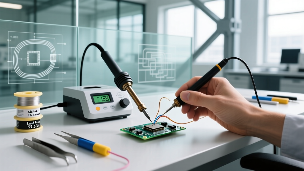
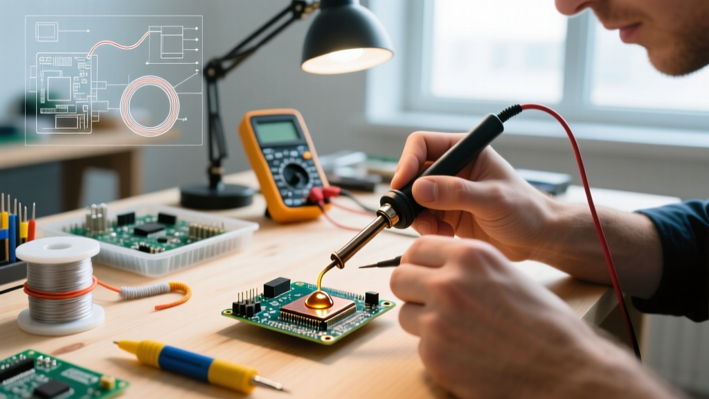
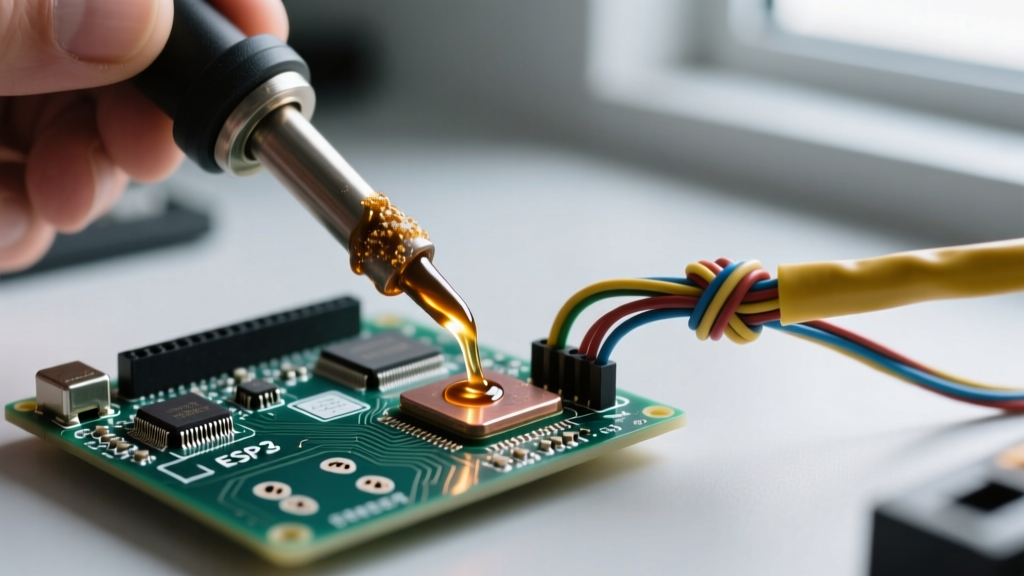
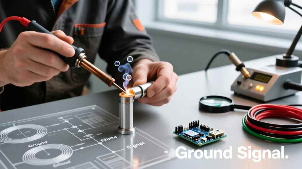
In the realm of electronics manufacturing and precision plumbing, thermal management is the dividing line between a reliable joint and catastrophic component failure. To understand modern soldering practices, we must first look at how the industry defines its thermal limits. According to the American Welding Society (AWS), soldering is categorized by the liquidus temperature of the filler metal. Soft soldering utilizes alloys that melt below 450°C (842°F), whereas hard soldering (brazing and silver soldering) occurs above this threshold. Consequently, the maximum temperature at which soft soldering is done is strictly bounded by this metallurgical ceiling, though practical application limits are significantly lower to protect delicate substrates.
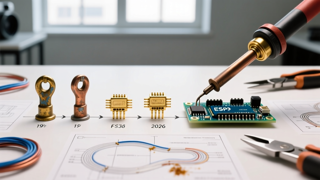
Historically, technicians were taught that the maximum temperature at which soft soldering is done is 400°C (752°F) at the tool tip. Exceeding this threshold does not merely risk burning the operator; it fundamentally alters the chemical structure of the flux, degrades the copper pads, and induces micro-fractures in the printed circuit board (PCB) laminate. As we trace the evolution of soldering from the mid-20th century to the high-density interconnect (HDI) landscape of 2026, the tools, alloys, and thermal profiles have shifted dramatically, even if the foundational definition of 'soft soldering' remains intact.
The Tin-Lead Golden Age (1950s–2005): Lower Heat, High Reliability
For over half a century, the electronics industry relied almost exclusively on eutectic tin-lead alloys, specifically Sn63/Pb37 (63% tin, 37% lead). This alloy was a metallurgical marvel for its time, boasting a sharp eutectic melting point of exactly 183°C (361°F). Because the alloy transitioned from solid to liquid without passing through a plastic (semi-solid) phase, it minimized the risk of cold joints caused by micro-movements during cooling.
Thermal Profiles of the Tin-Lead Era
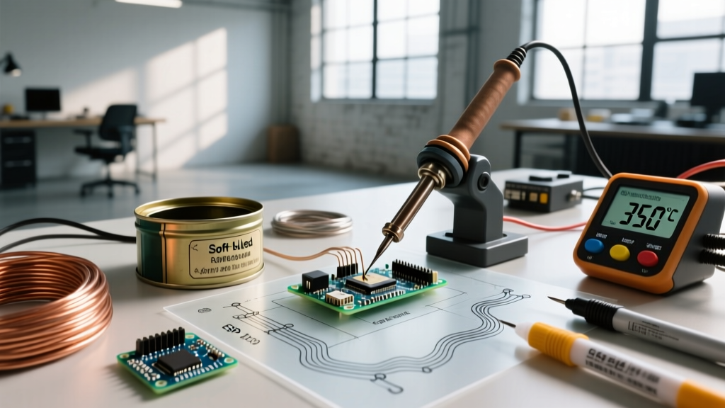
During this era, the thermal envelope was relatively forgiving. A typical soldering iron, such as the iconic Weller WTCPN series with its magnastat temperature control, was set between 315°C and 350°C (600°F–662°F). The delta-T (temperature difference) between the iron tip and the solder's melting point was roughly 130°C to 160°C. This provided ample thermal headroom to quickly wet the joint without instantly vaporizing the rosin-based fluxes (RMA) of the time.
- Standard Iron Temp: 315°C – 350°C
- Flux Activation Window: 150°C – 220°C
- Substrate Tolerance: Standard FR-4 (Tg 130°C) could withstand brief exposure to 350°C without delamination due to the rapid wetting speed of leaded solder.
The maximum temperature at which soft soldering was done during this period rarely needed to exceed 360°C. The high thermal conductivity of lead, combined with aggressive rosin fluxes, meant that dwell times on sensitive components like early integrated circuits (ICs) were kept under two seconds.
The RoHS Revolution (2006–Present): Pushing the Thermal Envelope
The pivotal moment in soldering history arrived with the enforcement of the Restriction of Hazardous Substances (RoHS) Directive by the European Union. The mandate to eliminate lead from consumer electronics forced the industry to adopt lead-free alternatives, fundamentally rewriting the rules of thermal management.
The SAC305 Challenge
The industry largely standardized on SAC305 (96.5% Tin, 3.0% Silver, 0.5% Copper). While SAC305 offered excellent mechanical strength, its melting point rose to 217°C (423°F)—a full 34°C higher than tin-lead. This shift forced technicians to push their equipment harder. To maintain a proper delta-T for rapid wetting, iron temperatures were pushed to 350°C–380°C (662°F–716°F).
However, pushing the maximum temperature at which soft soldering is done closer to 400°C introduced severe failure modes:
- Flux Burn-Off: Modern no-clean fluxes contain volatile activators that decompose rapidly above 380°C, leaving behind un-wetted oxides and causing severe solder balling.
- Pad Lifting and Delamination: The higher heat required to flow SAC305 often exceeded the Glass Transition Temperature (Tg) of standard FR-4 laminates (typically 130°C–150°C), causing Z-axis expansion and barrel cracking in plated through-holes (PTH).
- Tip Degradation: Lead-free solders are highly corrosive to iron-plated copper tips. Operating a Hakko T18 or Weller ET series tip at 400°C with SAC305 reduces tip lifespan by up to 70% compared to leaded operations.
Evolution of Soft Soldering Alloys and Maximum Operating Temperatures
The table below illustrates how the practical maximum tip temperature has evolved alongside alloy chemistry and industry standards like IPC J-STD-001.
| Era / Standard | Primary Alloy | Melting Point | Max Recommended Tip Temp | Primary Failure Mode if Exceeded |
|---|---|---|---|---|
| Pre-RoHS (Leaded) | Sn63/Pb37 | 183°C (361°F) | 350°C (662°F) | Component thermal shock, flux charring |
| Early RoHS (Standard) | SAC305 | 217°C (423°F) | 380°C (716°F) | Tip corrosion, PCB delamination |
| Modern Low-Temp (2020s) | Sn42/Bi58 | 138°C (280°F) | 250°C (482°F) | Bismuth joint fracturing, poor wetting |
| High-Reliability (Aero) | Sn96.5/Ag3.5 | 221°C (430°F) | 390°C (734°F) | Substrate burn, via barrel cracking |
Modern 2026 Thermal Management: Active Tips and Preheating
As we navigate the component densities of 2026, featuring 01005 (0.4mm x 0.2mm) passives and ultra-fine-pitch Ball Grid Arrays (BGAs), the brute-force method of simply turning up the soldering iron dial is obsolete. The industry has realized that the maximum temperature at which soft soldering is done should be managed through thermal equilibrium rather than peak tip heat.
The Shift to Active Cartridge Systems
Traditional soldering stations (e.g., the $125 Weller WE1010 or $110 Hakko FX-888D) rely on a thermocouple placed behind the heating element, resulting in a thermal lag when the tip contacts a massive ground plane. To combat this, high-end manufacturers like JBC and Metcal introduced active cartridge systems. In a JBC CD-2BQE station (retailing around $480), the thermocouple and heater are integrated directly into the C245 tip. This allows the system to detect a temperature drop and inject current in milliseconds, allowing the technician to set the dial to a safer 340°C while maintaining the thermal mass required to flow SAC305 on a multi-layer motherboard.
Bottom Preheating: Lowering the Delta-T
For complex rework, the modern standard is to use an IR or hot-air bottom preheater (such as the Hakko FR-830). By bringing the entire PCB ambient temperature up to 120°C–150°C, the soldering iron only needs to supply an additional 100°C to reach the SAC305 liquidus point. This drastically lowers the required tip temperature, keeping it well below the 400°C danger zone, preserving the flux chemistry, and preventing thermal shock to silicon dies.
Frequently Asked Questions (FAQ)
Is 450°C considered soft soldering?
No. According to international metallurgical standards, 450°C (842°F) is the exact threshold that separates soft soldering from hard soldering (brazing). If your filler metal requires 450°C or higher to melt, you are brazing, not soft soldering.
Can I use a 400°C iron for all lead-free electronics?
While 400°C will melt lead-free solder, it is generally discouraged for prolonged use on standard FR-4 PCBs. At 400°C, the flux activators in no-clean wire solder degrade almost instantly, leading to poor wetting and oxidized joints. It is better to use a 360°C–380°C tip with proper thermal mass or a preheater.
Why does my soldering iron tip turn black and stop working at high temps?
This is known as 'tip oxidation.' When an iron-plated copper tip is held above 380°C, especially with lead-free alloys, the iron plating rapidly oxidizes and dissolves into the tin. Once the iron layer is compromised, the molten solder will no longer wet the tip, rendering it useless.
Expert Takeaway: The history of soft soldering is not just a timeline of alloys; it is a continuous negotiation between metallurgy and material science. While the absolute maximum temperature at which soft soldering is done is capped below 450°C by definition, the practical limit for preserving modern 2026 microelectronics is firmly anchored at 380°C. Mastering thermal transfer—through tip geometry, active heating, and preheating—is far more critical than raw temperature.