
The Audio Engineer's Dilemma: Build vs. Buy
For studio owners, live sound technicians, and DIY audio enthusiasts, the decision of whether to buy pre-assembled interconnects or to start soldering XLR cables in-house is a persistent dilemma. While purchasing off-the-shelf cables from brands like Mogami or Pro Co offers immediate plug-and-play reliability, the economics and customization benefits of building your own can be overwhelmingly attractive—provided you have the right framework for making the decision. In 2026, with global copper prices continuing to fluctuate and supply chain lead times for custom studio wiring extending, understanding the true cost-benefit ratio of in-house cable fabrication is more critical than ever.
This decision framework will guide you through the financial break-even points, metallurgical choices, tooling prerequisites, and common failure modes associated with soldering XLR cables, ensuring you make an informed choice for your specific audio environment.
Phase 1: The Financial Break-Even Analysis
The most common driver for soldering XLR cables is cost savings. However, many beginners fail to account for the initial capital expenditure (CapEx) required for professional-grade tooling and the hidden costs of material waste. To determine if DIY fabrication makes financial sense, we must compare the unit economics of bulk assembly versus retail pre-made cables.
Material Cost Breakdown (2026 Market Estimates)
Let's examine the cost of building a standard 20-foot XLR cable using industry-standard components: Neutrik NC3MXX and NC3FXX connectors, and Canare L-4E6S Star Quad microphone wire.
- Neutrik XX Series Connectors: ~$4.85 per pair (Male + Female)
- Canare L-4E6S Star Quad Wire: ~$1.35 per foot ($27.00 for 20 ft)
- Consumables (Solder, Heat Shrink, Flux): ~$0.75 per cable
- Total DIY Cost per 20ft Cable: $32.60
By contrast, a retail 20-foot Mogami Gold Studio XLR cable retails for approximately $65.00 to $75.00. On a per-cable basis, the savings are roughly $35.00. However, you must amortize the cost of your soldering station, wire strippers, and multimeter.
| Production Volume | Total DIY Cost (Inc. $250 Tooling) | Total Retail Cost (Pre-Made) | Net Savings / Loss | Verdict |
|---|---|---|---|---|
| 5 Cables | $413.00 | $350.00 | -$63.00 (Loss) | Buy Pre-Made |
| 20 Cables | $902.00 | $1,400.00 | +$498.00 | DIY Highly Recommended |
| 50 Cables | $1,880.00 | $3,500.00 | +$1,620.00 | DIY Mandatory for ROI |
Decision Rule: If your studio or stage requires fewer than 10 custom-length cables, buy pre-made. If you are wiring a live snake, patching a large studio rack, or replacing a touring inventory of 20+ cables, soldering XLR cables in-house yields a massive return on investment.
Phase 2: Tooling and Metallurgy Decisions
You cannot achieve broadcast-grade reliability with a $15 hardware store soldering iron. Audio connectors require precise thermal management to prevent melting the internal plastic insulators of the XLR chassis while ensuring proper wetting of the brass/silver-plated contacts.
Selecting the Right Solder Alloy
The choice of solder dictates your working temperature and joint longevity. You have two primary paths:
- Leaded (Sn60Pb40): Kester 44 remains the gold standard for DIY audio. With a melting point of 188°C (370°F), it flows beautifully, creates shiny, easily inspectable joints, and is highly forgiving for beginners. We recommend a 0.031-inch (0.8mm) diameter wire with a rosin core.
- Lead-Free (SAC305): Composed of 96.5% Tin, 3% Silver, and 0.5% Copper. Required for commercial RoHS compliance, SAC305 melts at a higher 217°C (422°F) and results in duller joints that can be mistaken for cold solder joints by the untrained eye. It also accelerates tip oxidation.
Iron and Tip Selection
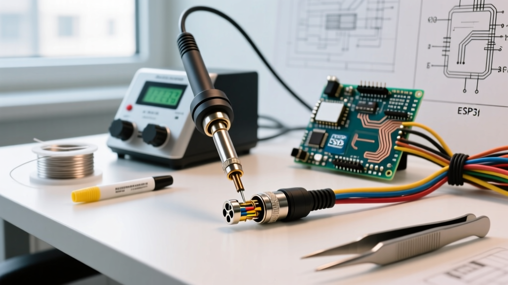
For soldering XLR cables, a temperature-controlled station like the Weller WE1010NA or Hakko FX-888D is mandatory. Set your iron to 350°C (662°F) for leaded solder. Use a chisel tip (e.g., Weller ETA or Hakko T18-D24) rather than a conical tip. The flat surface area of a chisel tip transfers heat to the XLR solder cup in 1.5 to 2 seconds, whereas a conical tip will linger for 5+ seconds, risking thermal damage to the Neutrik insert.
Phase 3: The Pinout and Shield Management Matrix
Adhering to the Audio Engineering Society (AES) standards for pinouts is non-negotiable. The standard AES XLR pinout is:
- Pin 1: Ground / Shield
- Pin 2: Hot (Positive / Non-Inverting)
- Pin 3: Cold (Negative / Inverting)
Pro-Tip on Star Quad Combing: If you are using Star Quad wire (like Canare L-4E6S), you have four inner conductors and a dense braided shield. You must 'comb' the shield braid using a dental pick or specialized combing tool to separate the copper strands into a single, cohesive drain wire. Twisting the shield by hand creates a bulky knot that will not fit inside the Neutrik XX series boot and can cause Pin 1 to short against the metal chassis.
Ground Lift Scenarios
When soldering XLR cables for stage snakes to combat ground loops, technicians sometimes employ a 'Pin 1 Lift' at the female (receiving) end. This means Pin 1 is connected to the shield at the male end, but left unconnected (floating) at the female end, with the shield wrapped in heat shrink to prevent accidental contact. Warning: Never lift Pin 1 on cables used for phantom power (48V), as this can cause severe RF interference and instability in condenser microphones.
Phase 4: Edge Cases and Failure Mode Troubleshooting
Even with the best tools, soldering XLR cables introduces specific failure modes that pre-molded or factory-assembled cables rarely exhibit. Understanding these edge cases is vital for quality control.
1. The 'Cold Joint' and Thermal Runaway
A cold joint occurs when the solder melts onto the iron tip and bridges to the XLR cup, but the cup itself never reaches the temperature required for metallurgical bonding. This results in a high-resistance connection that will eventually crack under physical stress, causing intermittent audio dropouts. Solution: Always apply the iron tip to the XLR cup first for 1 second, then feed the solder into the cup, not onto the iron.
2. Strain Relief Chuck Failure
The Neutrik XX series features a polyamide chuck that clamps down on the cable jacket when the boot is threaded on. A catastrophic failure occurs when the chuck bites into the inner wire insulation rather than the outer PVC jacket. This leaves the delicate solder joints to bear the entire mechanical weight of the cable when pulled. Solution: Strip exactly 22mm of the outer jacket, ensuring the chuck sits squarely on the thick outer PVC when tightened.
3. Solder Splatter and Pin 2/3 Shorts
XLR solder cups are positioned mere millimeters apart. If you use too much solder, or if flux boils and spatters, a microscopic bridge can form between Pin 2 and Pin 3. This will result in phase cancellation (a thin, hollow sound) or complete signal silence. Solution: Use a multimeter in continuity mode to test Pin 2 against Pin 3, and Pin 1 against the outer metal shell, before screwing the boot onto every single cable.
Final Verdict: When to Execute the Framework
Soldering XLR cables is a highly rewarding skill that offers immense financial and logistical benefits for high-volume audio environments. If you are outfitting a permanent studio installation, building a 32-channel stage snake, or maintaining a touring rig, the CapEx of a Weller station and bulk Canare wire pays for itself within the first 15 cables. However, if you only need a few standard-length interconnects for a home podcasting setup, the time investment and tooling costs do not justify the DIY route. Evaluate your volume, respect the AES pinout standards, and prioritize thermal discipline to achieve factory-level reliability in your own workshop.