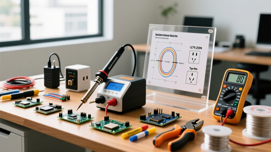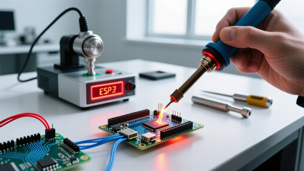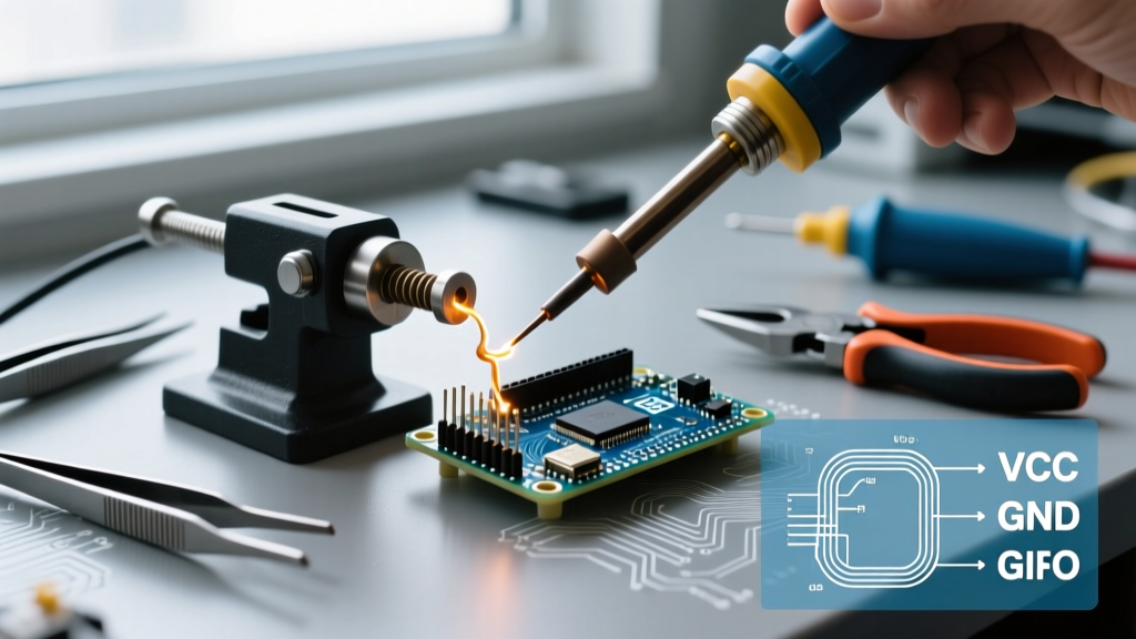

The Critical Role of a Soldering Vise in Modern Assembly
As surface-mount device (SMD) components shrink and high-density interconnect (HDI) PCBs become the standard in 2026, the humble soldering vise—often called a 'third hand' or PCB holder—has transitioned from a luxury to an absolute necessity. Whether you are using a heavy-duty Panavise Model 201, a flexible Hakko CHP HP-1, or a modular helping-hands rig, mechanical stability directly impacts your solder joint reliability. However, even premium vises suffer from grip slippage, thermal transfer issues, and joint stiffness over time. This comprehensive FAQ and troubleshooting guide addresses the most common failure modes encountered by electronics technicians and DIY engineers.
Soldering Vise FAQ: Setup, Selection, and Standards
What exactly qualifies as a soldering vise versus a standard bench vise?
A standard machinist bench vise is designed for high-torque clamping of raw metals, featuring hardened steel jaws that will instantly crush a fiberglass PCB or scrape off delicate copper traces. A dedicated soldering vise utilizes low-pressure, wide-surface-area clamping mechanisms. Models like the Weller WLSK200 or Panavise 201 use specialized nylon, silicone, or brass jaws designed to distribute clamping force evenly across a 1.6mm FR4 board edge without inducing micro-fractures in the substrate or vias.
Are ESD-safe jaws mandatory for modern microcontroller work?
Yes. If you are handling bare CMOS chips, MOSFETs, or sensitive RF modules outside of a strictly controlled ionized environment, electrostatic discharge (ESD) is a primary failure vector. Standard 3D-printed PLA or generic acrylic jaws can generate triboelectric charges exceeding 2,000V simply through friction. Always verify that your vise jaws are manufactured from carbon-impregnated, ESD-safe nylon or PEEK (Polyether ether ketone), which safely dissipates static charges to ground via the vise's metal chassis, provided the chassis itself is grounded to your workstation's ESD mat.
How much clamping pressure is safe for standard and flexible PCBs?
According to the IPC J-STD-001 standard for soldered electrical assemblies, mechanical stress must be minimized to prevent pad lifting and trace delamination. For standard 1.6mm FR4 boards, a clamping pressure of 5 to 10 PSI along the board edge is sufficient to resist the lateral force of a soldering iron. For flexible PCBs (polyimide) or ultra-thin 0.8mm boards, you should use a zero-point vacuum holder or specialized soft-silicone jaw pads to prevent substrate buckling entirely.
Troubleshooting Grip Slippage and PCB Spin
Nothing ruins a delicate 0402 SMD soldering session faster than the board spinning when you apply the iron tip. Slippage is usually a symptom of material degradation or improper surface area distribution, not necessarily a broken tool.
Diagnostic Flowchart: Why is my board rotating?
- Check the Jaw Material: Are the jaws hardened plastic or worn metal? Hard plastics lose their coefficient of friction when exposed to repeated flux fumes and heat.
- Inspect for Flux Glaze: Run your fingernail across the jaw surface. If it feels smooth and tacky, rosin-based flux residue has created a lubricating layer.
- Evaluate Edge Contact: Are you clamping a routed cutout or an uneven board edge? Point-loads on irregular edges will act as a pivot point.
- Test the Tension Knob: Does the main threaded spindle offer continuous resistance, or does it 'skip' under load?
Step-by-Step Fix for Worn Tension Knobs and Glazed Jaws
If your vise uses a threaded spindle (common in Panavise and budget Amazon clones), the internal nylon insert nut often strips or accumulates debris. Disassemble the spindle and clean the threads with isopropyl alcohol (IPA). Apply a microscopic amount of PTFE-based dry lubricant—never use petroleum grease, which attracts abrasive dust and degrades plastic components.
For glazed jaws, avoid using wire brushes or sandpaper, which will ruin the ESD-safe carbon matrix embedded in the nylon. Instead, use a stiff brass brush and a dedicated PCB cleaner like Techspray Purity CL to dissolve the rosin without damaging the jaw texture. For persistent slippage, adhere 2mm thick high-temperature silicone tape (rated for 300°C) to the inner jaw faces. This dramatically increases the friction coefficient while protecting the board edges.
Thermal Management: Heatsinking vs. Heat Trapping
A frequent point of confusion among hobbyists and junior technicians is whether a soldering vise acts as a helpful heatsink or a detrimental heat trap. The answer depends entirely on the thermal conductivity of the jaw material and the mass of the component being soldered.
Expert Insight: When soldering large ground planes or aluminum-core MCPCBs (common in high-power LED arrays), the board itself acts as a massive heatsink, pulling heat away from your iron tip. If your vise jaws are highly conductive, they will exacerbate this issue, leading to cold solder joints and prolonged dwell times that violate IPC reflow profiles.
Jaw Material Properties Comparison Matrix
| Material | ESD Safe? | Thermal Conductivity | Max Temp Rating | Best Use Case |
|---|---|---|---|---|
| ESD Nylon | Yes | Low (Insulator) | 150°C | General PCB assembly, SMD work |
| High-Temp Silicone | No (Usually) | Very Low | 300°C+ | Delicate edges, flex-PCBs, preventing scratches |
| Machined Brass | N/A (Conductive) | High | 400°C+ | Heavy wire tinning, mechanical anchoring |
| PEEK Polymer | Yes (Specialty) | Low | 250°C | Aerospace, high-reliability SMD |
As noted by the NASA Electronic Parts and Packaging (NEPP) Program guidelines on thermal workmanship, localized heating must be controlled to prevent thermal shock to ceramic components like MLCCs (Multi-Layer Ceramic Capacitors). If you are using brass jaws to hold a board while soldering near an MLCC, the brass will rapidly wick heat laterally, potentially cracking the capacitor's internal dielectric. Always isolate the clamping zone from sensitive components using thermal barrier tape (polyimide/Kapton).
Maintenance: Fixing Stiff Joints and Alignment Drift
Ball-and-socket articulating arms, like those found on the Hakko CHP or various 'helping hands' rigs, rely on friction to hold heavy boards in a fixed Z-axis position. Over time, these joints either become impossibly stiff or develop 'creep,' where the weight of the PCB slowly pulls the arm downward during soldering.
Restoring Ball-and-Socket Fluidity and Lock
The most common cause of joint creep is the accumulation of vaporized flux inside the socket housing. When flux aerosolizes at 350°C (typical for SAC305 lead-free profiles), it settles into the mechanical gaps of the vise joints, creating a sticky, hardened residue.
- For Stiff Joints: Do not force the joint with pliers; you will snap the internal retaining clips. Apply a few drops of 99% IPA directly into the joint gap and work it back and forth to dissolve the flux. Follow up with a dry PTFE spray.
- For Loose/Creeping Joints: If cleaning doesn't restore friction, the internal PTFE or nylon washer has worn down. Disassemble the joint and insert a custom-cut shim of 0.5mm brass stock or apply a thin layer of high-viscosity rosin paste to increase the friction coefficient temporarily.
Dealing with Warped Silicone Pads
Silicone jaw pads are excellent for grip but are notorious for warping when exposed to stray iron tips or accidental contact with a hot-air rework station nozzle. Once a silicone pad warps, it creates uneven pressure points that can snap brittle PCBs. If your silicone pads develop a 'cupped' shape, you can attempt to flatten them by clamping them between two flat aluminum plates and submerging the assembly in boiling water for three minutes, followed by an immediate cold-water quench while still clamped. However, for professional environments adhering to strict Adafruit and industry soldering guidelines, replacing warped pads annually is the most cost-effective way to prevent catastrophic board damage.
Summary: Optimizing Your Workholding Strategy
A soldering vise is not merely a clamp; it is a critical thermal and mechanical interface in your assembly workflow. By selecting the correct jaw material for your specific substrate, maintaining the friction surfaces free of flux glaze, and understanding the thermal dynamics of your workholding setup, you eliminate the variables that lead to cold joints, lifted pads, and ESD failures. Treat your vise maintenance with the same rigor as your soldering iron tip care, and your first-pass yield rates will improve dramatically.