
The Case for a Soldering Alternative in Modern Electronics
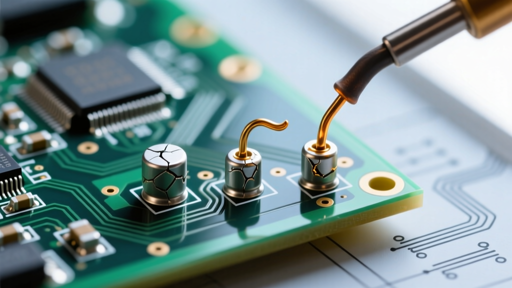
While traditional tin-lead and SAC305 (lead-free) soldering remains the backbone of electronics assembly, it is not a universal solution. Thermal shock to sensitive components, the inability to rework flexible printed circuits (FPCs) without delamination, and the strict requirements for high-vibration aerospace environments often demand a reliable soldering alternative. In 2026, advanced mechanical and chemical interconnects offer comparable or superior electrical performance without the application of heat.
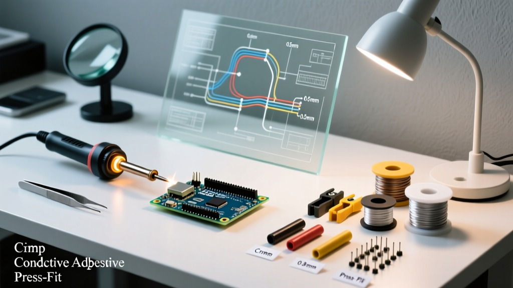
This decision framework evaluates the four most viable alternatives—crimping, conductive adhesives, press-fit technology, and wire wrapping—providing exact specifications, tooling costs, and failure mode analyses to help you select the right method for your specific application.
Evaluating the Core Alternatives
1. Cold Welding: Precision Crimping
Crimping relies on mechanical deformation to create a gas-tight 'cold weld' between a wire and a terminal. When executed correctly, the metal-to-metal contact exhibits lower electrical resistance than the wire itself and completely prevents oxygen from reaching the core, halting corrosion.
- Best For: High-vibration environments (automotive, aerospace), field repairs, and high-current wire-to-board connections.
- Tooling & Cost: Entry-level ratcheting crimpers like the IWISS SN-28B cost around $25 and handle standard Dupont/JST terminals. However, for mission-critical Micro-Fit or Mini-Fit terminals, OEM hand tools like the Molex 63811-1000 series are required, costing upwards of $450.
- Specifications: According to IPC/WHMA-A-620 standards, a proper 22 AWG crimp must withstand a minimum pull-force of 15 to 20 lbs without the wire slipping or breaking at the crimp barrel.
2. Chemical Interconnects: Conductive Adhesives
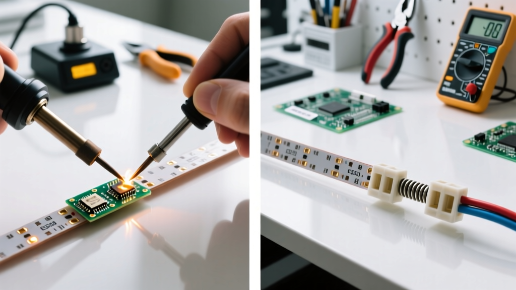
Conductive epoxies and silicone adhesives use a polymer matrix loaded with metallic particles (usually silver or copper) to conduct electricity. They cure at room temperature or with mild heat, making them the premier soldering alternative for heat-sensitive components like thermistors, flexible substrates, and RFID tags.
- Best For: Flexible PCBs, surface-mount LED die attach, and heat-sensitive sensors.
- Material Profile: A standard like MG Chemicals 8331 (Silver Conductive Epoxy) costs approximately $45 for a 50g dual-cartridge. It offers a volume resistivity of 0.0006 ohm-cm.
- Curing Parameters: Requires 24 hours at 25°C or an accelerated 2 hours at 65°C. Note that conductive adhesives generally lack the shear strength of metallurgical solder joints and should not be used as the sole mechanical anchor for heavy components.
3. Mechanical Interference: Press-Fit / Compliant Pin Technology
Press-fit connectors utilize compliant pins (such as the 'eye-of-the-needle' design) that deform elastically when pushed into a plated through-hole (PTH) on a PCB. This creates a massive surface-area gas-tight connection without any thermal stress to the board.
- Best For: High-density backplanes, automotive ECUs, and thick multi-layer PCBs where wave or reflow soldering would cause excessive thermal warping.
- Tolerances: Success relies entirely on PCB manufacturing precision. The PTH diameter must typically be held to a tolerance of ±0.05mm. If the hole is too large, retention force drops; if too small, the plating barrels will crack.
4. Legacy Prototyping: Wire Wrapping
Wire wrapping involves tightly coiling 30 AWG or 28 AWG solid-core Kynar-insulated wire around a square, sharp-edged metal post. The corners of the post bite into the wire, creating multiple redundant gas-tight connections.
- Best For: Complex point-to-point prototyping and legacy aerospace systems.
- Tooling: Requires a precision wire wrap tool (e.g., Vector Electronics T144, approx. $60) and a specialized stripping tool to avoid nicking the solid core.
- Reliability: Data from the NASA Electronic Parts and Packaging (NEPP) Program historically validates wire wrapping for high-reliability space applications, provided the wrap includes at least 1.5 turns of insulated wire above the bare wire turns for strain relief.
The Decision Matrix: Which Method Wins?
Use the following matrix to quickly identify the optimal soldering alternative based on your project's primary constraints.
| Constraint / Requirement | Optimal Alternative | Runner-Up | Methods to Avoid |
|---|---|---|---|
| Extreme Vibration / Shock | Precision Crimping | Wire Wrapping | Conductive Adhesives |
| Heat-Sensitive Substrate (FPC/PET) | Conductive Adhesives | Press-Fit (if PTH exists) | All Thermal Methods |
| High-Density Backplane Assembly | Press-Fit Pins | None | Wire Wrapping, Crimping |
| Field Repair (No Power/Heat) | Crimping | Conductive Adhesives | Press-Fit |
| Low-Cost Rapid Prototyping | Wire Wrapping | Crimping | Press-Fit (requires specific PCB) |
Environmental and Failure Mode Analysis
Understanding how these alternatives fail is critical for design engineering. As outlined by the IPC standards body and independent reliability testing, each method has distinct edge cases.
Crimping Failure Modes
The most common failure in crimping is fretting corrosion caused by an under-crimp. If the tooling is not properly calibrated, the wire strands can move microscopically within the barrel under vibration, generating oxide dust that increases resistance. Conversely, an over-crimp cuts into the wire strands, reducing the effective cross-sectional area and creating a localized hot-spot under high current loads.
Conductive Adhesive Failure Modes
Silver-filled epoxies are susceptible to galvanic corrosion when used to bond dissimilar metals (e.g., silver epoxy on a copper pad in a high-humidity environment). Furthermore, adhesives suffer from creep under continuous mechanical stress. If a heavy capacitor is attached solely with conductive glue, thermal cycling will eventually cause the polymer matrix to yield, breaking the electrical path.
Press-Fit Failure Modes
Press-fit failures almost always originate at the PCB fabrication stage. Barrel cracking occurs if the insertion force exceeds the tensile strength of the copper plating inside the hole. Additionally, pad lifting can occur if the annular ring adhesion to the FR4 substrate is compromised during the high-force insertion process.
Cost and Tooling Investment Breakdown
When transitioning away from a standard $40 soldering station, the capital expenditure for alternative tooling must be factored into your project budget.
- Crimping Setup: $150 - $600. You will need a dedicated ratcheting crimper for every terminal pitch you use (e.g., 1.25mm, 2.0mm, 2.54mm), plus a high-quality wire stripper like the Knipex 12 42 195 ($75).
- Conductive Adhesive Setup: $60 - $120. Initial cost is low (epoxy cartridges and static mixing nozzles), but recurring material costs are high. Silver epoxy expires and requires refrigeration, adding to long-term overhead.
- Press-Fit Setup: $200 - $1,500+. While the pins are cheap, you must invest in a precision arbor press or a specialized pneumatic insertion tool to ensure the force is applied perfectly perpendicular to the board. Hand-pressing large connectors will result in bent pins.
- Wire Wrapping Setup: $80 - $150. A manual wire wrap tool, strip tool, and spools of 30 AWG Kynar wire are highly affordable and require zero maintenance.
Expert Insight: Never use standard pliers to crush a crimp terminal. A true gas-tight crimp requires a ratcheting mechanism that ensures the terminal is deformed to the exact volumetric displacement required for the wire gauge. If the tool releases before the cycle is complete, the joint is compromised.
Final Verdict
Selecting the right soldering alternative is not about finding a universal replacement for solder, but rather matching the interconnect physics to your environmental constraints. For dynamic, high-vibration wire harnesses, invest in OEM-grade crimping tooling. For delicate flexible circuits and heat-sensitive die-attach, silver conductive epoxies provide an unmatched low-thermal-stress bond. For high-reliability backplanes, press-fit compliant pins eliminate thermal warping entirely. By applying this decision framework, you can eliminate thermal bottlenecks and mechanical weak points in your next electronics assembly.