
The Metallurgical Reality of Soldering Thermocouples
Unlike standard electrical wiring, soldering a thermocouple is not just about achieving electrical continuity; it is about preserving the delicate Seebeck effect that generates the temperature-dependent millivolt signal. While NIST guidelines on thermocouple metrology emphasize that welding (TIG, laser, or resistance) is the gold standard for creating the measurement junction, soldering remains a necessary technique for low-temperature applications, extension wire terminations, and PCB pad integrations.
However, introducing a third metal (solder) into a thermoelectric circuit introduces severe failure risks if the metallurgy and thermal dynamics are misunderstood. This guide dives deep into the specific failure modes of soldered thermocouple junctions and provides actionable troubleshooting frameworks for DIY electronics engineers and industrial technicians.
The Golden Rule of Thermocouple Soldering: You can only solder the actual measurement junction if your maximum operating temperature remains at least 50°C below the solidus (melting) point of your chosen solder alloy. For high-temperature sensors (Type K, Type J), soldering is strictly reserved for the cold-junction compensation (CJC) reference end or PCB termination points.
Troubleshooting Matrix: 4 Common Soldered Junction Failures
When a soldered thermocouple reads erratically, drifts, or fails entirely, the root cause usually falls into one of four categories. Use this diagnostic matrix to identify your failure mode.
| Failure Symptom | Root Cause | Metallurgical / Thermal Explanation | Actionable Fix |
|---|---|---|---|
| Signal drifts as ambient temp rises | Solder Alloy Melting / Softening | The solder alloy is approaching its plastic deformation range, altering the contact resistance and introducing parasitic thermoelectric EMFs. | Switch to a high-temp alloy like Sn95/Sb5 (Melting point: 235°C) or Pb97.5/Ag1.5/Sn1 (Melting point: 309°C). |
| Sluggish response time (High Latency) | Thermal Shunting (Solder Blob too Large) | A large mass of solder increases the thermal capacitance ($C$) of the junction. The time constant ($\tau = R \times C$) spikes, delaying heat transfer to the actual thermoelectric metals. | Wick away excess solder. The final junction bead must not exceed 1.5x the diameter of the bare thermocouple wire. |
| Erratic noise / Open circuit | Cold Joint / Flux Inclusion | Insufficient wetting on Chromel/Alumel (Type K) or Constantan due to rapid oxidation. Flux residue trapped inside the joint acts as a thermal and electrical insulator. | Use a highly active RMA (Rosin Mildly Activated) flux. Pre-tin the wires individually before twisting and soldering the final junction. |
| Consistent offset error (e.g., +2.4°C) | Galvanic Corrosion / Third Metal Gradient | According to the Law of Intermediate Metals, solder is harmless ONLY if the entire solder bead is at a uniform temperature. A thermal gradient across a large solder bead generates an offset voltage. | Minimize bead size and ensure the junction is in an isothermal environment. Clean off all corrosive water-soluble fluxes immediately. |
The "Law of Intermediate Metals" and Solder Errors
A frequent question in precision analog signal conditioning is whether the tin/lead or SAC305 solder alloy will corrupt the microvolt-level signal of the thermocouple. The Law of Intermediate Metals states that inserting a third metal into a thermocouple circuit will not affect the net EMF, provided that the two junctions where the third metal meets the dissimilar metals are at the exact same temperature.
The Troubleshooting Catch: In a welded bead, the junction is microscopic and isothermal. In a hand-soldered bead using a 60W iron, the solder blob might be 2mm long. If one side of the solder blob is exposed to a heat source while the other is shielded, a temperature gradient forms across the solder itself. Because the solder is an alloy of Tin and Silver/Copper, it has its own Seebeck coefficient relative to the thermocouple wires. This gradient generates a parasitic voltage, manifesting as a permanent offset error in your temperature readings.
Step-by-Step: Terminating Type T Wire to a Copper PCB Pad
Type T (Copper / Constantan) is the most forgiving thermocouple for soldering, commonly used in cryogenic and food-processing applications (up to 370°C). Here is the exact procedure for terminating 24 AWG Omega Engineering TT-T-24-SLE wire to a prototype PCB without inducing thermal EMF errors.
- Preparation: Strip exactly 4mm of the PFA insulation from both the Copper and Constantan wires. Do not use a thermal wire stripper; the heat can alter the crystalline structure of the Constantan, changing its local Seebeck coefficient.
- Flux Application: Apply a small drop of Kester 951 No-Clean liquid flux to the bare wires. Avoid water-soluble fluxes (like MG Chemicals 8341) unless you have an ultrasonic cleaner to remove 100% of the residue, as ionic contamination causes severe galvanic corrosion on Constantan.
- Pre-Tinning (Crucial): Set your soldering station (e.g., Hakko FX-951) to 320°C. Using Sn63/Pb37 eutectic solder, pre-tin the Copper wire and the Constantan wire separately. Constantan resists wetting; you may need to hold the iron on the Constantan for 2-3 seconds longer than the Copper.
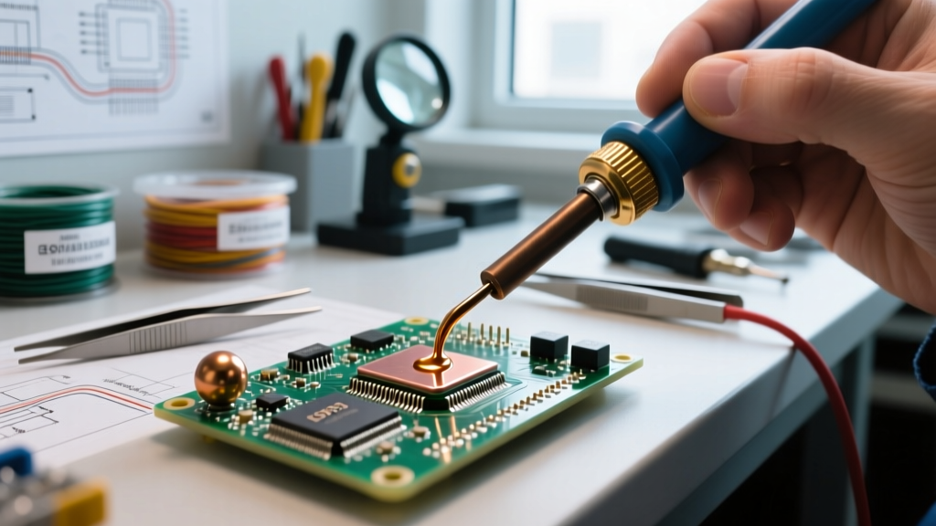
- PCB Pad Tinning: Pre-tin the copper PCB pad. Ensure the pad has a flat surface; do not leave a domed blob of solder.
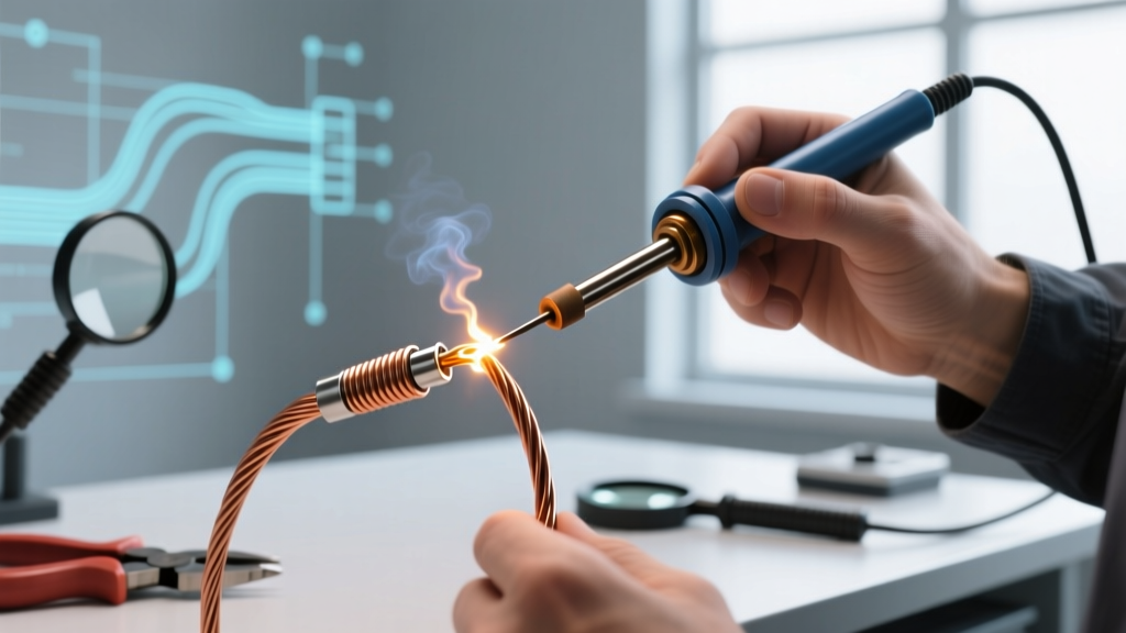
- Final Termination: Place the pre-tinned thermocouple wire flat against the pre-tinned PCB pad. Apply the iron for exactly 1.5 to 2 seconds until the solder flashes and flows. Remove heat immediately.
- Strain Relief: Because soldered thermocouple wires are highly susceptible to mechanical fatigue (which causes micro-fractures and resistance spikes), apply a drop of neutral-cure RTV silicone over the termination point. Never use cyanoacrylate (Super Glue), as it outgasses and degrades the solder joint over time.
Tooling & Consumables Guide (2026 Market Pricing)
To achieve reliable thermocouple solder joints, your tooling must offer rapid thermal recovery. Standard 40W irons will cause cold joints on 20 AWG or thicker thermocouple wire due to the high thermal mass of the metal.
- Soldering Station: Weller WE1010NA ($120 - $140) or Hakko FX-951 ($290 - $330). You need a station that recovers to 340°C within 3 seconds of the tip touching the wire.
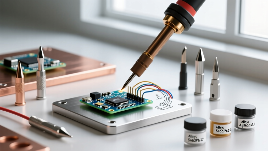
- Solder Alloy for Low-Temp (Type T): Kester 245 No-Clean Core (Sn63/Pb37). Melting point 183°C. Cost: ~$35 per 1lb spool.
- Solder Alloy for Medium-Temp (Type J / Extension): Indium Corp. Sn95/Sb5. Melting point 235°C. Excellent creep resistance. Cost: ~$85 per 1lb spool.
- Flux: Kester 951 Liquid Flux (No-clean, low-solid). Essential for wetting the nickel-rich Chromel wires found in Type K extensions. Cost: ~$18 per 2oz bottle.
FAQ: Rapid-Fire Thermocouple Soldering Questions
Can I solder a Type K thermocouple junction?
Practically, no. Type K (Chromel/Alumel) is rated for continuous use up to 1,260°C. There is no commercially viable solder alloy that can survive these temperatures. Even high-lead solders (Pb97.5/Ag1.5/Sn1) melt at 309°C. If you attempt to solder a Type K measurement junction, the solder will melt and destroy the sensor long before the thermocouple reaches its operational range. You must use a capacitive discharge (CD) welder or a micro-TIG torch for Type K junctions.
Why is my soldered Constantan wire turning green and brittle?
This is galvanic corrosion driven by acidic flux residue. Constantan (a Copper-Nickel alloy) is highly susceptible to corrosive attack from halide-based or water-soluble fluxes. If you see a green, crusty oxidation forming at the solder joint within 48 hours, you failed to clean the flux. Switch to a high-purity RMA (Rosin Mildly Activated) flux or a verified no-clean flux like Kester 245, and ensure your cleaning solvent (e.g., isopropyl alcohol) is not just spreading the flux around, but physically removing it.
Does the polarity of the solder joint matter?
Yes, absolutely. The Seebeck effect is directional. For Type T, the Copper wire is positive (+) and the Constantan is negative (-). For Type K, the non-magnetic Chromel wire is positive (+) and the magnetic Alumel wire is negative (-). If you reverse the polarity at your soldered PCB termination, your temperature readings will inversely correlate (dropping as the environment heats up). Always verify polarity with a neodymium magnet (Alumel and Constantan are slightly magnetic; Chromel and Copper are not) before applying solder.
When to Solder vs. When to Weld: A Decision Framework
Use this quick-reference matrix to determine your joining method based on the application parameters.
| Parameter | Soldering Recommended | Welding (TIG/Laser/CD) Required |
|---|---|---|
| Max Operating Temp | < 150°C (Standard Sn63) or < 220°C (Sn95/Sb5) | > 250°C up to 1,700°C (Type B/R/S) |
| Application | PCB termination, cold-junction reference, low-temp HVAC sensors | Measurement junctions in ovens, kilns, exhaust manifolds, and fluid baths |
| Wire Gauge | 24 AWG to 30 AWG (Fine wire for PCBs) | 14 AWG to 24 AWG (Heavy wire for industrial probes) |
| Response Time Need | Moderate (Seconds to Minutes) | Critical (Milliseconds to Sub-second) |
By respecting the metallurgical limits of your solder alloys and strictly managing thermal gradients across the junction, you can successfully integrate thermocouples into custom PCB designs and low-temperature monitoring rigs without sacrificing signal integrity.