
The Thermal Paradox: Why Soldering to a Battery is Controversial
In the landscape of custom electronics manufacturing, medical devices, and industrial IoT deployments, power source reliability is non-negotiable. While high-volume electric vehicle (EV) and consumer electronics manufacturers rely almost exclusively on automated spot welding or ultrasonic welding for lithium-ion cell interconnects, a significant segment of the industry still relies on manual or semi-automated soldering. However, soldering to a battery introduces a severe thermal paradox: the temperature required to melt solder significantly exceeds the thermal tolerance of the battery cell itself.
Understanding the metallurgy, thermal dynamics, and industry standards governing this process is critical for electrical engineers and assembly technicians. A single mistake during the soldering process can lead to degraded cell capacity, venting, or catastrophic thermal runaway.
The 130°C Threshold and Thermal Runaway
The primary danger when soldering to a lithium-ion cell (such as standard 18650, 21700, or prismatic formats) lies in the internal separator. These micro-porous membranes, typically made of polyethylene (PE) or polypropylene (PP), are designed to shut down ion flow and melt at approximately 130°C to 150°C.
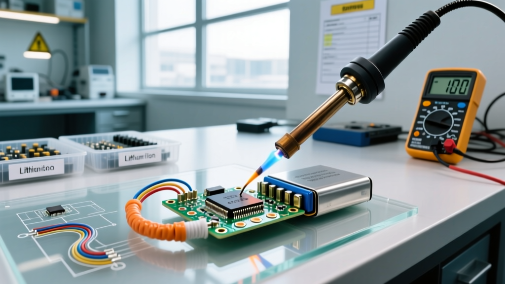
Conversely, standard lead-free solder alloys (like SAC305) melt at 217°C, and even traditional leaded solder (Sn60Pb40) melts at 183°C. Because the metal casing and nickel-plated steel tabs of a battery act as excellent thermal conductors, applying a 350°C soldering iron directly to the cell terminal risks transferring enough heat to the core to shrink or melt the separator. As detailed in Battery University's safety analysis, internal short circuits resulting from separator damage can trigger immediate thermal runaway, venting toxic gases and potentially causing fires.
When Industry Actually Solders to Batteries
Given the risks, why do industrial applications still utilize soldering? The answer lies in production volume, cell chemistry, and mechanical requirements.
- Low-Volume & Prototyping: For aerospace, military, and specialized medical devices producing fewer than 5,000 units annually, the capital expenditure for automated ultrasonic welders ($20,000+) or pneumatic spot welders ($10,000+) is unjustifiable.
- Thick Gauge Wiring: Spot welding struggles to create reliable, high-current connections to thick silicone wires (e.g., 10 AWG to 14 AWG) without specialized, expensive projection welding setups. Soldering easily wicks into stranded copper, creating a robust mechanical and electrical bond.
- NiMH and LiPo with Pre-Attached Tabs: Nickel-Metal Hydride (NiMH) cells are far more thermally tolerant than Li-ion. Additionally, many industrial LiPo (Lithium Polymer) pouch cells come from the factory with pre-soldered nickel tabs designed specifically to act as thermal buffers for secondary soldering operations.
Expert Insight: In high-reliability medical assemblies, we often specify soldering over spot welding for heavy-gauge discharge leads because the solder joint provides superior mechanical strain relief against vibration, provided the thermal exposure is strictly limited to under two seconds per joint.
Precision Equipment and Metallurgy
To successfully execute a solder joint on a battery terminal without damaging the cell, you must use equipment with massive thermal recovery rates and the correct metallurgical profile.
The Soldering Station
Standard 40W to 60W hobbyist irons are dangerous for battery work because they lose heat rapidly upon contact with the battery's metal casing. The operator is then forced to hold the iron in place for 5 to 10 seconds to achieve flow, guaranteeing internal cell damage. Industrial environments utilize high-wattage, active-tip systems:
- JBC CD-2BQE with C245 Cartridges (Approx. $650): The heating element is located millimeters from the tip. It recovers its 350°C setpoint in under 2 seconds, allowing the technician to melt the solder and remove the iron almost instantly.
- Hakko FX-952 (Approx. $380): Utilizes T18 tips with a ceramic heater core. Excellent for mid-tier production, though slightly slower in thermal recovery than JBC.
Solder Alloy Selection
| Alloy Type | Composition | Melting Point | Industrial Use Case for Batteries |
|---|---|---|---|
| Sn60Pb40 (Leaded) | 60% Tin, 40% Lead | 183°C (361°F) | Preferred. Lower melting point means less heat transfer to the cell. Excellent wetting on nickel tabs. |
| SAC305 (Lead-Free) | 96.5% Sn, 3% Ag, 0.5% Cu | 217°C (422°F) | Avoid if possible. Requires higher iron temps (380°C+), increasing the risk of separator meltdown. |
| Sn43Pb43Bi14 | Tin, Lead, Bismuth | 144°C (291°F) | Niche. Used for highly sensitive components, but joints are brittle and fail under mechanical vibration. |
Flux Chemistry
Never use acid-core or water-soluble (OA) flux on battery terminals. The aggressive activators will corrode the nickel plating and seep into the battery seal, causing micro-shorts over time. Always use a No-Clean, Rosin Mildly Activated (RMA) flux, such as Kester 186 or MG Chemicals 8341. These provide enough activity to break through the nickel oxide layer without leaving conductive or corrosive residues.
The 2-Second Protocol: Step-by-Step Assembly
Industrial standard operating procedures (SOPs) for soldering to a battery mandate a strict sequence to minimize thermal dwell time.
- Mechanical Preparation: Lightly scuff the nickel-plated steel battery tab or casing with 400-grit sandpaper or a fiberglass scratch pen to remove surface oxidation. Wipe with 99% isopropyl alcohol.
- Wire Pre-Tinning: Strip the silicone wire (e.g., 16 AWG) and pre-tin it heavily with Sn60Pb40 solder. The wire should be fully saturated before it ever touches the battery.
- Thermal Sinking (Optional but Recommended): Clamp a copper alligator clip or specialized thermal heat-sink tweezers onto the battery tab between the solder joint and the cell body to absorb excess heat.
- Tab Pre-Tinning: Apply a small amount of RMA flux to the battery terminal. Touch the 350°C iron to the terminal and feed solder until a small, flat puddle forms. Time limit: 1.5 seconds.
- The Mating: Place the pre-tinned wire onto the pre-tinned tab. Touch the iron to the wire (not the battery) to reflow the joint. Time limit: 1.0 second. Hold the wire still until the solder crystallizes (approx. 2 seconds).
Failure Modes and Edge Cases
Even with proper equipment, specific failure modes plague inexperienced assembly teams:
- Cold Joints on Nickel: Nickel-plated steel is notoriously difficult to wet. If the iron temperature is too low, the solder will ball up and roll off the tab, tempting the operator to apply prolonged heat, which destroys the cell.
- Separator Shrinkage: If the iron is left on the positive terminal (which is directly connected to the internal cathode current collector) for more than 3 seconds, the heat travels deep into the jelly roll, causing the PE separator to shrink and trigger an internal short.
- Flux Dendrite Growth: In high-humidity industrial IoT deployments, failing to clean mildly activated flux residues can lead to electrochemical migration (dendrites) between the positive and negative terminals, resulting in parasitic drain and eventual short circuits.
Spot Welding vs. Soldering: An Industry Matrix
To determine the correct interconnect method for your 2026 production run, evaluate your requirements against this comparison matrix:
| Parameter | Resistance Spot Welding | Ultrasonic Welding | Manual Soldering |
|---|---|---|---|
| Capital Cost | $3,000 - $15,000 | $20,000 - $60,000 | $400 - $800 |
| Thermal Stress to Cell | Negligible (Milliseconds) | None (Friction-based) | High (Requires strict SOPs) |
| Wire Thickness Limit | Poor for thick stranded wire | Excellent for foils and thick wire | Excellent for heavy gauge wire |
| Production Volume | Medium to High | High (EV/Automotive) | Low (Prototyping/Medical) |
| Joint Inspection | Destructive peel test required | Visual and pull-test | Visual (IPC standards apply) |
IPC Compliance and Quality Assurance
For commercial and industrial electronics, battery pack assemblies must adhere to strict quality benchmarks. According to safety guidelines outlined by OSHA regarding lithium-ion battery hazards, thermal mismanagement during assembly is a primary catalyst for workplace battery incidents.
Furthermore, compliance with UL battery testing and safety standards requires that interconnects withstand specific vibration and thermal cycling tests without degradation. When soldering is the chosen method, assembly houses typically default to IPC-J-STD-001 (Requirements for Soldered Electrical and Electronic Assemblies) and IPC-A-610 (Acceptability of Electronic Assemblies) Class 3 (High-Reliability) standards. Class 3 mandates that solder joints exhibit proper wetting, a smooth fillet, and absolutely no evidence of thermal damage to the underlying substrate or component casing. If the battery's PVC shrink wrap is melted or blistered within a 5mm radius of the solder joint, the assembly is considered a defect and must be rejected.