
The Contenders: Static Soldering Pots vs. Dynamic Wave Systems
When transitioning from one-off prototyping to small-batch manufacturing (10 to 500 units), electronics labs and boutique manufacturers face a critical bottleneck: through-hole termination and wire preparation. While hand soldering with a high-quality iron like the Weller WE1010 is viable for a few boards, it introduces massive variability and labor costs at scale. This leaves two primary batch methods on the table: static soldering pots (dip pots) and dynamic benchtop wave soldering systems.
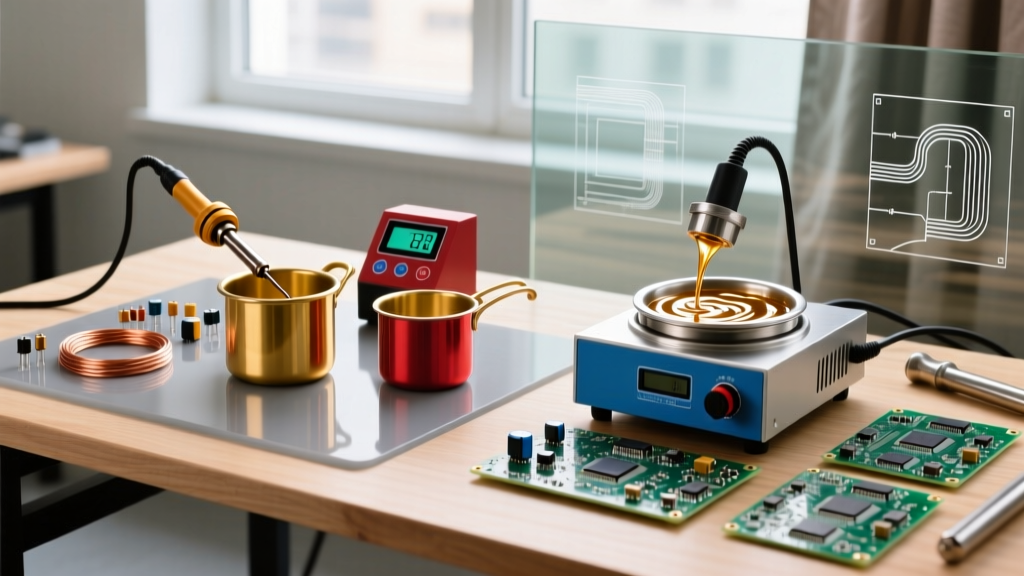
Understanding the metallurgical, financial, and operational differences between these methods is essential for optimizing your 2026 production line. A soldering pot, such as the industry-standard Hakko FX-300 or the compact Weller WSBP88, relies on a static bath of molten alloy. Conversely, a benchtop wave soldering machine utilizes an internal pump to create a localized, directional wave of solder. Both have distinct advantages, but their use cases rarely overlap.
Capital and Operational Cost Matrix
Before diving into technical capabilities, it is crucial to evaluate the financial footprint of each method. The barrier to entry for soldering pots is exceptionally low, making them a staple in university labs and startup workbenches.
| Feature | Benchtop Soldering Pot (e.g., Hakko FX-300) | Benchtop Wave Solder (e.g., ACE KIS / PACE) | Hand Soldering (Baseline) |
|---|---|---|---|
| CapEx (Initial Cost) | $150 - $280 | $4,500 - $12,000+ | $100 - $250 |
| OpEx (Power Draw) | ~100W - 300W | 1,000W - 2,500W (Heaters + Pumps) | 60W - 80W |
| Solder Capacity | 300g - 1,000g | 10kg - 40kg | N/A (Wire/Paste) |
| Dross Generation | Low (Static surface) | High (Agitated surface) | N/A |
| Maintenance | Minimal (Element replacement) | High (Pump impellers, nozzle cleaning) | Tip replacement |
| Best Application | Wire tinning, component dipping | Populated PCB through-hole assembly | Prototyping, rework |
Application 1: Wire Tinning and Harness Preparation
For wire tinning, stripping, and harness preparation, soldering pots are the undisputed champions. In aerospace, automotive, and high-end audio manufacturing, preparing hundreds of stranded wire ends requires uniform coating without damaging the insulation.
According to guidelines published by the NASA Electronic Parts and Packaging (NEPP) Program, proper wire tinning requires complete wetting of the stranded copper without allowing solder to wick under the wire insulation. A static soldering pot allows the operator to precisely control the dip depth and dwell time.
Preventing Insulation Melt-Back and Wicking
When using a soldering pot for wire prep, thermal management is your primary adversary. The temperature of the pot must be high enough to ensure rapid wetting (preventing prolonged heat exposure) but controlled enough to avoid melting the wire jacket.
- PVC Insulation: Highly susceptible to melt-back. Keep pot temperatures at the lower end of the alloy's working range (e.g., 240°C for Sn63/Pb37). Dwell time must not exceed 1.5 seconds.
- PTFE (Teflon) & Silicone: Withstand temperatures well over 260°C. These allow you to run the pot hotter (270°C+ for SAC305 lead-free alloys), ensuring instant wetting and zero insulation deformation.
- Wicking Prevention: Always strip the wire immediately before tinning. Oxidized copper requires aggressive fluxing and longer dwell times, which guarantees solder wicking under the jacket via capillary action.
Application 2: Through-Hole PCB Assembly
While you can use a soldering pot for PCB assembly via a technique called "drag soldering" or by using custom titanium jigs to dip entire boards, it is highly discouraged for modern electronics. This is where wave soldering takes over.
When a populated PCB is dragged across a static solder pot, the lack of directional flow leads to severe solder bridging between closely spaced pins (e.g., 0.1" pitch DIP ICs or dense terminal blocks). Furthermore, plunging a room-temperature FR4 fiberglass board into a 260°C static bath causes massive thermal shock, risking pad delamination and via barrel cracking.
"Thermal shock during soldering can cause internal fractures in plated through-holes (PTH). Preheating the assembly and utilizing a dynamic wave with controlled contact time is critical for maintaining IPC-A-610 Class 3 reliability standards." — IPC (Association Connecting Electronics Industries) Workmanship Guidelines.
Benchtop wave solderers solve this by incorporating IR preheat zones that slowly bring the PCB to 110°C-130°C before it contacts the solder wave. The pump-driven wave provides kinetic energy, pushing flux volatiles out of the barrel and pulling fresh solder up into the PTH, achieving the 75% barrel fill required for high-reliability Class 3 assemblies.
Metallurgy and Dross Management in 2026
The transition to lead-free manufacturing has fundamentally changed how we manage soldering pots. The most common lead-free alloy, SAC305 (Sn96.5/Ag3.0/Cu0.5), has a melting point of 217°C and an operating temperature of 255°C to 270°C.
At these elevated temperatures, tin oxidizes rapidly when exposed to air, forming a crusty layer of dross (tin oxide). In a static soldering pot, dross forms a protective blanket over the surface. Do not skim the dross continuously. Skimming exposes fresh molten tin to oxygen, accelerating the consumption of your expensive SAC305 bar solder. Instead, use a dross-reducing chemical powder or gel to separate the metallic tin from the oxide before skimming once per shift.
In contrast, wave soldering machines constantly agitate the surface, generating dross at a significantly higher rate. A benchtop wave machine running 8 hours a day can easily consume $50 to $100 worth of lead-free solder per week purely in dross waste, whereas a static pot used for wire tinning might generate less than $10 in dross over the same period.
Step-by-Step: Optimizing the Soldering Pot Workflow
If your primary application is wire tinning or dipping heavy through-hole lugs, follow this optimized workflow using a standard 300W soldering pot:
- Alloy & Temp Selection: Load the pot with Sn63/Pb37 (if leaded processes are permitted) and set the dial to 245°C. For RoHS-compliant SAC305, set the dial to 265°C. Allow 20-30 minutes for the thermal mass to stabilize.
- Flux Application: Dip the stripped wire end (typically 3mm to 5mm) into a mild RMA (Rosin Mildly Activated) liquid flux, such as Kester 186. Avoid highly acidic plumbing fluxes, which will corrode the copper strands over time.
- The Dip: Pierce the dross layer gently with the wire. Submerge the stripped section into the clean molten bath at a 45-degree angle.
- Dwell Time: Hold for exactly 1 to 2 seconds. You will feel a slight "pull" as the flux activates and the solder wets the copper. Do not agitate the wire wildly, as this introduces oxides into the bath.
- Withdrawal & Cooling: Pull the wire out in one smooth motion. Flick your wrist sharply once to shed excess solder droplets, preventing the formation of a bulky "solder ball" at the tip of the wire. Allow to air cool; do not quench in water, which can crack the solder joint.
Final Verdict: Choosing Your Method
The choice between soldering pots and wave soldering is not a matter of one being universally superior; it is strictly dictated by your physical product.
If your daily workflow involves preparing wiring harnesses, tinning heavy gauge battery cables, or pre-tinning component leads before automated insertion, a high-quality soldering pot (budget: $250) is the most efficient, cost-effective, and precise tool available. It offers unmatched control for manual dipping with minimal maintenance.
However, if you are manufacturing populated printed circuit boards with dense through-hole components, DIP switches, or multi-layer FR4, you must invest in a wave soldering system. The kinetic energy of the wave, combined with necessary preheating stages, is the only way to achieve IPC-compliant barrel fill without destroying your PCBs via thermal shock or bridging adjacent pins.