
The Core Dilemma: To Solder or Not to Solder?
When building custom wiring harnesses, repairing marine electronics, or extending low-voltage DC lines, the integrity of your wire joints dictates the reliability of the entire system. The practice of soldering splice wires is often romanticized as the ultimate standard for electrical connections. However, in 2026, modern mechanical and crimped alternatives have fundamentally shifted the landscape. Making the right choice requires a rigorous decision framework based on environment, vibration, wire gauge, and electrical codes.
A common and dangerous misconception is that solder provides mechanical strength. According to the National Electrical Code (NEC) Article 110.14(b), splices must be mechanically secure before soldering. Solder is strictly for electrical continuity and corrosion resistance. Relying on a blob of solder to hold two pulled wires together is a primary cause of field failures. For a deeper understanding of mechanical connection requirements, refer to the National Fire Protection Association's NEC guidelines.
The Soldering Splice Wires Decision Matrix
Use the following matrix to evaluate whether soldering, crimping, or push-in mechanical connectors are optimal for your specific application.
| Connection Method | Mechanical Strength | Vibration Resistance | Time per Splice | Material Cost (2026) | Ideal Use Case |
|---|---|---|---|---|---|
| Soldered Splice | Low (Relies on wire twist) | Poor (Fatigue at edge) | 2 - 4 minutes | $0.05 - $0.10 | Static PCB wires, audio, marine (with sealant) |
| Heat-Shrink Crimp | Very High | Excellent | 30 - 45 seconds | $0.35 - $0.60 | Automotive, aviation, high-vibration DC |
| Push-In (e.g., Wago 221) | High (Spring clamp) | Good | 10 - 15 seconds | $0.40 - $0.55 | AC Mains, junction boxes, solid/stranded mix |
Deep Dive: When Soldering Splice Wires is the Optimal Choice
Despite the rise of mechanical connectors, soldering remains unmatched for specific edge cases. You should default to soldering splice wires when dealing with:
- Marine and High-Humidity Environments: When paired with dual-wall adhesive-lined heat shrink (e.g., 3M MDT), a soldered joint prevents capillary action from wicking moisture into the stranded wire core.
- High-Frequency RF and Audio Signals: Mechanical crimps can introduce micro-variances in impedance. A smooth, flowed solder joint maintains signal integrity.
- Space-Constrained Harnesses: A properly flowed inline solder splice has a lower profile than a bulky crimp barrel, allowing for tighter bundle diameters.
Material Selection for 2026
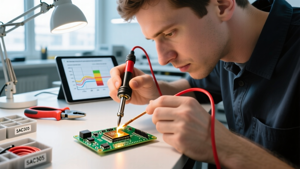
For general electronics and low-voltage DC, 63/37 Sn/Pb (Tin/Lead) eutectic solder remains the gold standard due to its sharp melting point (183°C / 361°F), which prevents cold joints during the transition phase. Kester 245 No-Clean Flux-Cored Wire (approx. $50 per pound in 2026) is the industry benchmark. If your project requires RoHS compliance, you must step up to SAC305 (Tin/Silver/Copper), which melts at 217°C (423°F) and requires a higher-wattage iron, such as the Hakko FX-888D set to 380°C to ensure adequate thermal recovery.
Expert Insight: Never use acid-core plumbing solder for electrical splices. The zinc chloride flux will aggressively corrode the copper strands over time, leading to high-resistance failures. Always use rosin-core or no-clean electronics flux.
Step-by-Step: Executing the Perfect Soldered Splice
If your decision framework points to soldering, execution is everything. The IPC J-STD-001 standard outlines strict requirements for soldered electrical assemblies, emphasizing wetting and contour visibility.
1. Preparation and Stripping
For 14 AWG to 22 AWG stranded wire, strip exactly 3/8 inch (9.5mm) of insulation. Use a precision thermal stripper or high-quality mechanical strippers (like the Knipex ErgoStrip) to avoid nicking the outer copper strands. A single nicked strand reduces the wire's tensile strength by up to 40%.
2. The Mechanical Twist (Lineman's Splice)
Cross the stripped wires in an 'X' shape. Twist them around each other tightly for at least 3 to 4 full turns. This mechanical interlock bears the physical stress, not the solder. Trim any sharp, protruding wire ends flush with flush-cut diagonal pliers to prevent them from piercing the heat shrink later.
3. Thermal Application
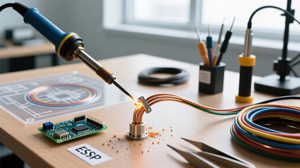
Apply the tip of your soldering iron to the wire, not the solder. Heat the copper for 2-3 seconds until it is hot enough to melt the solder on contact. Feed 63/37 solder into the joint opposite the iron. You should see the flux boil and the solder wick into the strands via capillary action. The ideal joint will look shiny and reveal the contour of the individual wire strands beneath the surface.
Critical Failure Modes to Avoid
Even experienced technicians fall into traps when soldering splice wires. Be vigilant against these specific failure modes:
- Cold Joints: Caused by moving the wire before the solder fully solidifies, or insufficient heat. The joint will look dull, grainy, or bulbous. In a vibrating environment, a cold joint will crack and arc.
- Flux Entrapment: If you use liquid or paste flux externally and fail to clean it, the residue can become conductive or corrosive over time, especially in high-humidity environments.
- Wicking Under Insulation: If you apply too much heat for too long, solder will wick up under the wire's insulation jacket. This turns the flexible stranded wire into a rigid, brittle solid right at the stress relief point, guaranteeing a fatigue break under vibration.
When to Pivot: High-Vibration and Mains Alternatives
If your decision matrix rules out soldering, you must select the correct alternative based on the voltage and environment.
Automotive and High-Vibration DC
For 12V/24V automotive or off-road applications, abandon soldering entirely. The constant vibration will cause the rigid soldered joint to fatigue and snap just outside the heat shrink. Instead, use adhesive-lined heat shrink crimps (e.g., Molex Perma-Seal 19164 series). You must use a proper ratcheting crimp tool (like the Titon THT-11) that applies the exact compression force required to cold-weld the copper to the brass barrel.
AC Mains and Junction Boxes
For 120V/240V AC household wiring, soldering is largely obsolete and often prohibited by local inspectors if used as the sole mechanical connection. The modern standard is the Wago 221 series lever-nut. The 221-413 (3-conductor) model handles 12 to 24 AWG, accommodates both solid and stranded wire simultaneously, and provides a gas-tight, maintenance-free connection in seconds. For a comprehensive look at mechanical connector code compliance, review the Electrical Contractor Magazine codes and standards section.
Final Verdict
Soldering splice wires is a precision technique reserved for static, low-voltage, or environmentally sealed applications where signal integrity and corrosion resistance are paramount. By applying this decision framework, you ensure that every joint you make is not only electrically sound but mechanically robust and compliant with modern engineering standards.