
Introduction to Photonic Soldering Hazards
Photonic soldering—encompassing laser diode reflow and intense pulsed light (IPL) systems—has revolutionized how we attach heat-sensitive components, flexible circuits, and micro-BGA packages. Unlike traditional conductive heating via a soldering iron or convective hot air, photonic systems deliver highly localized, non-contact thermal energy. While this precision is invaluable for modern 2026 microelectronics, it introduces a unique matrix of safety hazards that standard electronics workbench protocols simply do not cover.
From invisible near-infrared (NIR) radiation and ultra-fine flux ablation particulates to catastrophic thermal runaway, operating a photonic soldering workstation requires specialized engineering controls. This guide details the exact safety best practices, hardware requirements, and personal protective equipment (PPE) necessary to operate Class 4 laser soldering systems safely and in compliance with OSHA laser safety guidelines.
The Invisible Hazard: Laser Radiation & Ocular Safety
The most immediate danger in photonic soldering is the laser source. Most industrial and desktop laser soldering stations utilize Near-Infrared (NIR) diode lasers, typically at 808 nm, 915 nm, or 980 nm wavelengths. More recently, 450 nm (blue) diode lasers have gained traction for direct copper heating.
Because 808 nm to 980 nm light is invisible to the human eye, your natural aversion response (the blink reflex) will not trigger. A specular reflection off a shiny solder pad or a gold-plated RF shield can instantly cause permanent retinal burns or blindness. According to the Laser Institute of America, any soldering laser exceeding 500 mW is classified as a Class 4 laser, requiring stringent administrative and engineering controls.
Wavelength Interaction & Eyewear Matrix
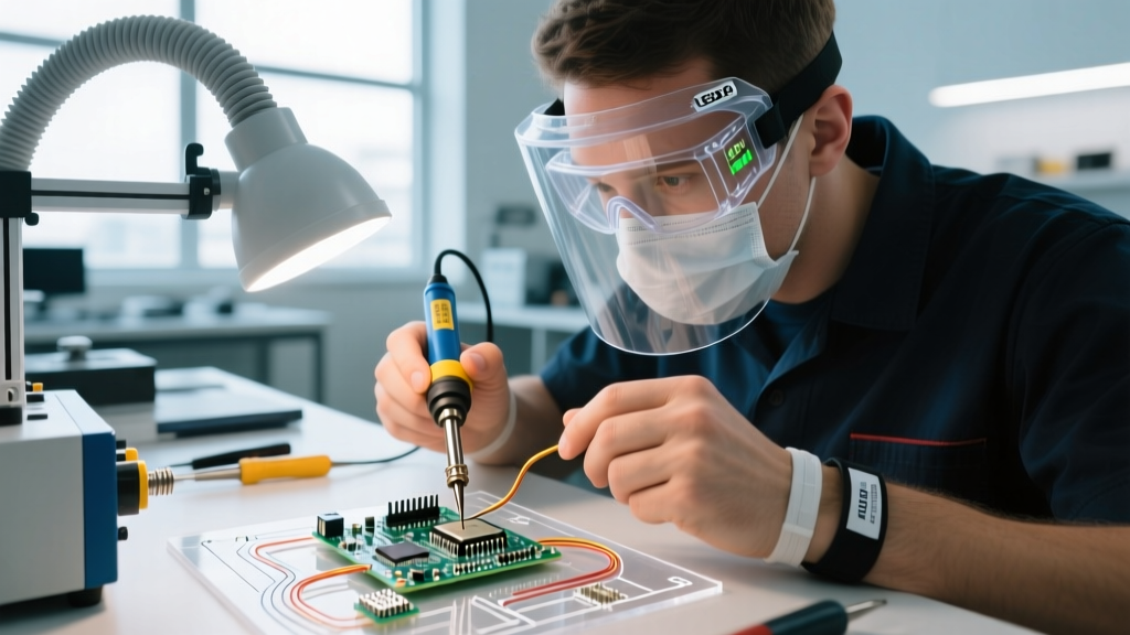
Standard welding goggles or generic 'laser safety glasses' are entirely ineffective and dangerous for photonic soldering. Eyewear must be rated for the exact wavelength of your diode array with a sufficient Optical Density (OD). An OD of 6 reduces laser intensity by a factor of 1,000,000.
| Laser Wavelength | Primary Target Material | Minimum Required Eyewear OD | Visible Indicator Beam? |
|---|---|---|---|
| 450 nm (Blue) | Copper traces, dark substrates | OD 5+ (Visible Blue Block) | Yes (Beam is visible) |
| 808 nm (NIR) | Solder paste, general pads | OD 6+ at 808nm | No (Requires 650nm pilot) |
| 980 nm (NIR) | Silicon absorption, deep joints | OD 7+ at 980nm | No (Requires 650nm pilot) |
Critical Safety Warning: Never rely solely on the visible red pilot laser (usually 650 nm) to indicate the status of the main NIR beam. Hardware interlocks and beam shutters can fail, leaving the invisible 980 nm beam active while the pilot laser is off.
Fume Extraction: Managing Photonic Flux Ablation
When a high-intensity laser strikes solder paste, the flux activators and rosin bases do not merely melt; they undergo rapid thermal decomposition and ablation. This photonic vaporization creates a plume of ultra-fine particulate matter (PM0.1 and PM2.5) and volatile organic compounds (VOCs) that behave differently than the smoke generated by a standard 350°C soldering iron.
Why Standard Desk Extractors Fail
A standard benchtop HEPA fan (e.g., a $150 Hakko FA-400) is fundamentally inadequate for photonic soldering for three reasons:
- Capture Velocity: Laser ablation plumes eject upward at high velocities. Low-static-pressure fans cannot capture the plume before it disperses into the operator's breathing zone.
- Filter Loading: The microscopic carbonized flux particles rapidly blind standard HEPA filters, dropping airflow by 60% within weeks.
- VOC Penetration: Vaporized rosin and glycol-ether solvents pass straight through HEPA media, requiring deep-bed activated carbon.
Spec'ing the Right Extraction System
For a closed-loop photonic workstation, you must integrate an industrial-grade fume extractor. Look for systems like the BOFA AD Oracle 3 or Weller Zero Smog 4V.
Required Specifications:
- Airflow: Minimum 350 CFM (cubic feet per minute) at the capture nozzle.
- Static Pressure: >30 mbar to overcome resistance in 4-inch flexible ducting.
- Filtration Stages: Pre-filter (F8) -> Main HEPA (H13/H14) -> Deep-bed Activated Carbon (minimum 10 kg of carbon for VOC adsorption).
- Nozzle Placement: The extraction hood must be positioned exactly 2 to 4 inches from the laser focal point, utilizing a coaxial or close-proximity lateral capture design.
Thermal Runaway and Substrate Ignition
Photonic soldering relies on closed-loop temperature control, typically using an integrated infrared (IR) pyrometer to measure the joint temperature in real-time and adjust laser power dynamically. However, a major failure mode occurs due to emissivity shifts.
The Emissivity Trap in Closed-Loop Soldering
IR pyrometers calculate temperature based on the thermal radiation emitted by the target. The emissivity of a surface dictates how accurately the pyrometer reads the true temperature.
When SAC305 (lead-free) solder paste transitions from a dull, powdery solid (emissivity ~0.85) to a shiny, molten liquid (emissivity ~0.15), the pyrometer suddenly 'sees' less radiation. The control algorithm incorrectly assumes the joint has cooled down and aggressively ramps up the laser power to compensate. This results in massive thermal overshoot, instantly vaporizing the solder, scorching the FR-4 substrate, or delaminating polyimide flex circuits.
Preventing Substrate Ignition: Step-by-Step Calibration
To prevent catastrophic thermal runaway and potential bench fires, operators must calibrate the pyrometer feedback loop for every new board geometry:
- Apply High-Emissivity Coating: For initial profiling, apply a microscopic dot of high-temp, high-emissivity paint (e.g., Aerodag G or specialized IR calibration tape) adjacent to the target pad.
- Map the Reflow Curve: Run the laser profile while logging the pyrometer data alongside a physical K-type thermocouple attached to a sacrificial test coupon.
- Implement Power Clamping: In the laser control software, set a hard 'Maximum Power Limit' (e.g., cap the 980nm laser at 45W, even if the system is rated for 100W). This prevents the PID controller from outputting maximum wattage during the liquidus emissivity drop.
- Utilize Dual-Wavelength Pyrometers: For high-end 2026 workstations, upgrade to a two-color (ratio) pyrometer, which calculates temperature based on the ratio of two wavelengths, rendering the measurement largely immune to emissivity shifts and partial occlusions from flux smoke.
Hardware Interlocks and Enclosure Standards (IEC 60825-1)
Under IPC guidelines and international laser safety standard IEC 60825-1, Class 4 laser soldering systems must be fully enclosed during operation. Open-beam photonic soldering on a standard open workbench is a severe safety violation in any commercial or educational environment.
Mandatory Engineering Controls
- Safety Interlock Switches: All access doors and maintenance panels must feature dual-channel, fail-safe magnetic interlocks (e.g., Schmersal or Sick brand). Opening a door must physically cut power to the laser diode driver within milliseconds, bypassing software controls.
- Viewing Windows: Enclosure windows must be constructed from laser-rated polycarbonate or glass that blocks the specific operating wavelength (OD 6+), while still allowing visible light transmission for camera monitoring.
- Emission Indicator Lights: A highly visible, redundant LED beacon (usually red) must be mounted on the exterior of the enclosure, illuminating only when the laser diode is actively receiving current.
- Key Switch & Remote Interlock: The main power must be controlled by a physical key switch. Additionally, a remote interlock connector must be wired to the room's master emergency stop (E-Stop) and door switches.
Buyer’s Checklist: Spec’ing a Safe Photonic Workstation
When procuring a photonic soldering system in 2026, safety features should be line-item budget considerations, not optional add-ons. Below is a realistic cost breakdown for a fully compliant, safe workstation setup.
| System Component | Safety Requirement / Specification | Estimated Cost (USD) |
|---|---|---|
| Desktop Laser Soldering Base Unit | 980nm Diode, Closed-Loop Pyrometer, 50W | $18,000 - $28,000 |
| Class 4 Safety Enclosure | IEC 60825-1 Compliant, Interlocked Doors, OD6+ Glass | $3,500 - $6,000 |
| Industrial Fume Extractor | 350+ CFM, HEPA + 10kg Carbon Bed (e.g., BOFA) | $4,000 - $5,500 |
| Wavelength-Specific Eyewear | OD 7+ at 980nm (e.g., Phillips Safety, NoIR) | $80 - $150 per pair |
| Laser Safety Signage & E-Stop Wiring | ANSI Z136.1 Warning Labels, Hardwired Room E-Stop | $200 - $500 |
Frequently Asked Questions (FAQ)
Can I use standard welding goggles or shade-5 glasses for NIR laser soldering?
No. Welding goggles are designed to block broad-spectrum visible light and UV/IR radiation from an electric arc. They do not provide the targeted Optical Density (OD) required to stop a concentrated, monochromatic 980 nm laser beam. Using welding goggles for Class 4 NIR laser work will result in severe eye injury.
Is photonic soldering safe for lead-free SAC305 pastes?
Yes, but it requires precise thermal profiling. SAC305 requires a higher liquidus temperature (217°C to 220°C) and a longer time-above-liquidus (TAL) than leaded Sn63Pb37. Because photonic heating is incredibly rapid, you must carefully tune the laser's ramp-up and soak phases to allow the flux activators to clean the pads before the solder melts, preventing cold joints and solder balling.
What happens if the extraction system fails mid-reflow?
Modern, high-end photonic workstations feature airflow sensors integrated into the safety interlock loop. If the fume extractor's static pressure drops below the safe threshold (indicating a clogged filter or motor failure), the hardware interlock will immediately disable the laser firing circuit to prevent the operator from being exposed to unextracted, concentrated flux ablation plumes.