
The SMT Dilemma in Modern Electronics
As through-hole components continue their slow march toward obsolescence in consumer and commercial electronics, mastering soldering SMT (Surface Mount Technology) components is no longer optional for DIYers, hardware startups, and repair technicians. In 2026, the 0402 (1.0mm x 0.5mm) package is the baseline standard for passives, while 0201 and 01005 packages are increasingly common in dense IoT and wearable designs. Simultaneously, fine-pitch QFPs (Quad Flat Packages) and bottom-terminated QFNs (Quad Flat No-leads) dominate microcontroller footprints.
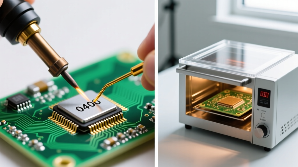
When assembling prototypes or small batches (10 to 50 boards), makers face a critical methodological fork in the road: Do you invest in a high-end precision soldering setup for hand soldering, or do you adopt a benchtop reflow oven and solder paste workflow? Both methods have distinct cost structures, skill curves, and failure modes. This guide provides a deep-dive technical comparison to help you choose the optimal SMT assembly method for your lab.
Method 1: Hand Soldering SMT Components
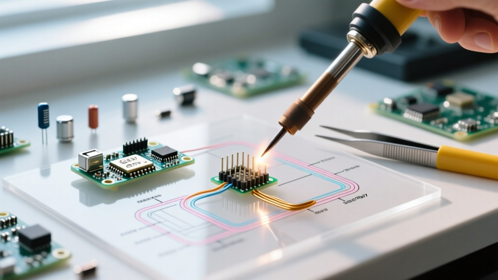
Hand soldering SMT relies on direct thermal transfer via a micro-soldering iron. Contrary to popular belief, with the right optics and thermal management, hand soldering 0.4mm pitch QFPs and 0402 resistors is highly reliable and often faster for single-board prototyping than setting up stencils and reflow profiles.
Essential Toolchain & Pricing (2026 Estimates)
- Soldering Station: Quick 861DW ($260) or Hakko FX-951 ($230). You need a station that recovers heat in under 2 seconds to handle the thermal mass of ground planes.
- Microscope: AmScope SM-4TP Trinocular Zoom ($250). A 7x-45x magnification range is mandatory for inspecting 0402 joints and fine-pitch IC pins.
- Flux: Chip Quik SMD291AX No-Clean Tacky Flux ($25/syringe). Never attempt SMT hand soldering without additional flux; the factory flux core in thin solder wire is insufficient for drag soldering.
- Solder Wire: 0.3mm diameter Sn63/Pb37 (leaded) or SAC305 (lead-free). Thicker wire floods fine-pitch pads instantly.
- Desoldering Wick: Goot Wick CP-2060 ($12). Essential for fixing bridges via capillary action.
Core Techniques: Drag Soldering vs. Tack-and-Solder
For fine-pitch ICs (like an LQFP-64 with 0.5mm pitch), drag soldering is the industry standard. You apply a generous bead of tacky flux to the pads, tin the iron tip with a large solder blob, and drag it across the pins at a 45-degree angle. The flux breaks the surface tension, allowing the solder to flow only onto the copper pads and component leads, leaving the gaps clean.
For discrete passives (0603 and 0402), the tack-and-solder method is preferred. You tin one pad, use fine-tipped tweezers (like the Hakko CHP-7-SA) to place the component, and tack it down with the iron. Once secured, you solder the opposite pad. According to the SparkFun SMD Soldering Guide, maintaining a clean iron tip with brass wool between every single joint is the primary difference between a reliable connection and a cold joint.
Method 2: Benchtop Reflow & Hotplate Soldering
Reflow soldering eliminates the physical touch of an iron, relying instead on a controlled thermal profile to melt pre-applied solder paste. This is the undisputed champion for batch production and bottom-terminated components like QFNs and BGAs (Ball Grid Arrays) where an iron simply cannot reach the pads.
Stencils, Paste, and Thermal Profiling
The reflow workflow begins with applying solder paste through a stencil. For 0.4mm pitch QFPs and 0402 passives, a 100µm (0.004-inch) thick stainless steel stencil is required to prevent paste slumping and subsequent bridging. Polyimide (Kapton) stencils are cheaper ($30) but degrade quickly and struggle with fine apertures; stainless steel ($80-$120) is the 2026 standard for reliable results.
For heating, makers generally choose between two tools:
- Mini Hotplates (e.g., Miniware MHP50 - $60): Ideal for boards under 50x50mm. The MHP50 allows programmable thermal profiles, letting you set a precise preheat soak (150°C) and peak reflow temperature (225°C for leaded, 245°C for lead-free).
- DIY Reflow Ovens (e.g., T-962A - $180): Necessary for larger boards. The stock T-962A requires community firmware mods (like the Unified Flow controller) to fix its erratic factory temperature sensors and achieve IPC-compliant thermal profiles.
Head-to-Head Comparison Matrix
| Feature | Hand Soldering SMT | Benchtop Reflow / Hotplate |
|---|---|---|
| Initial Setup Cost | $550 - $650 (Station + Scope + Tweezers) | $200 - $350 (Hotplate/Oven + Stencils + Paste) |
| Throughput (10 Boards) | Low (Hours of meticulous manual labor) | High (Minutes for reflow, though pick-and-place takes time) |
| 0201 / 01005 Passives | Extremely Difficult (Requires micro-soldering mastery) | Excellent (Paste surface tension self-aligns components) |
| QFN / BGA Components | Poor (Cannot access bottom thermal pads reliably) | Excellent (Mandatory method for hidden pads) |
| Primary Failure Mode | Solder Bridging & Thermal Pad Lift | Tombstoning & Solder Balling |
Diagnosing SMT Failure Modes
Understanding how and why SMT joints fail is critical for passing IPC J-STD-001 inspection criteria, whether you are soldering by hand or using an oven.
Hand Soldering Failures
- Solder Bridging: Caused by using wire that is too thick or insufficient flux. Fix: Apply liquid or tacky flux and drag a clean, dry iron tip across the bridge to pull the excess solder away via capillary action.
- Pad Delamination: Applying a 400°C iron to a 0402 pad for more than 3 seconds will melt the FR4 epoxy bond, lifting the pad off the board. Fix: Use lower temperatures (320°C for leaded) and rely on high thermal-recovery stations rather than brute heat.
Reflow Failures
- Tombstoning: A passive component stands up on one end like a gravestone. This occurs when the solder paste on one pad melts before the other, pulling the component upward via surface tension. Fix: Ensure symmetrical pad geometry and extend the 'soak' zone of your thermal profile (150°C-180°C for 90 seconds) to equalize board temperature before hitting the liquidus point.
- QFN Thermal Pad Voiding: Solder paste trapped under a QFN's large center ground pad boils, creating voids or pushing the IC upward, causing the outer pins to fail to wet. According to a Texas Instruments Application Note on QFN soldering, you must use a 'windowed' or 'cross-hatched' stencil aperture for the thermal pad, reducing the paste coverage area by 20-30% to allow flux gases to escape during reflow.
Expert Insight: If you are forced to hand-solder a QFN component without a reflow oven, use a high-quality hot air rework station (like the Quick 861DW's air handpiece) set to 380°C with a low airflow rate (15 L/min) to avoid blowing the component off the board. Pre-heat the board to 120°C on a hotplate first to minimize thermal shock.
Expert Verdict: Which Method Should You Choose?
The choice between hand soldering SMT and reflow methods ultimately depends on your component density and production volume.
Choose Hand Soldering if: You are primarily doing board repairs, reworking prototypes, or assembling single boards featuring standard 0603/0402 passives and leaded QFP/SOIC microcontrollers. The high initial investment in a microscope and premium soldering station pays dividends in versatility, allowing you to fix mistakes instantly without re-baking the entire PCB.
Choose Reflow if: Your designs heavily feature bottom-terminated QFNs, BGAs, or dense arrays of 0201 passives. If you are producing batches of 10+ identical IoT sensor boards, the time saved by stenciling paste and running a batch through a T-962A or MHP50 hotplate will vastly outweigh the manual pick-and-place time, yielding factory-grade, uniform solder joints.
In the modern electronics lab of 2026, the most capable makers do not choose just one; they maintain a hybrid workflow, utilizing reflow for the initial population of dense passive arrays and QFNs, and relying on a precision hand iron for final connector soldering, rework, and debugging.