
The Core Dilemma: Soldered Copper vs. Crimped Terminations
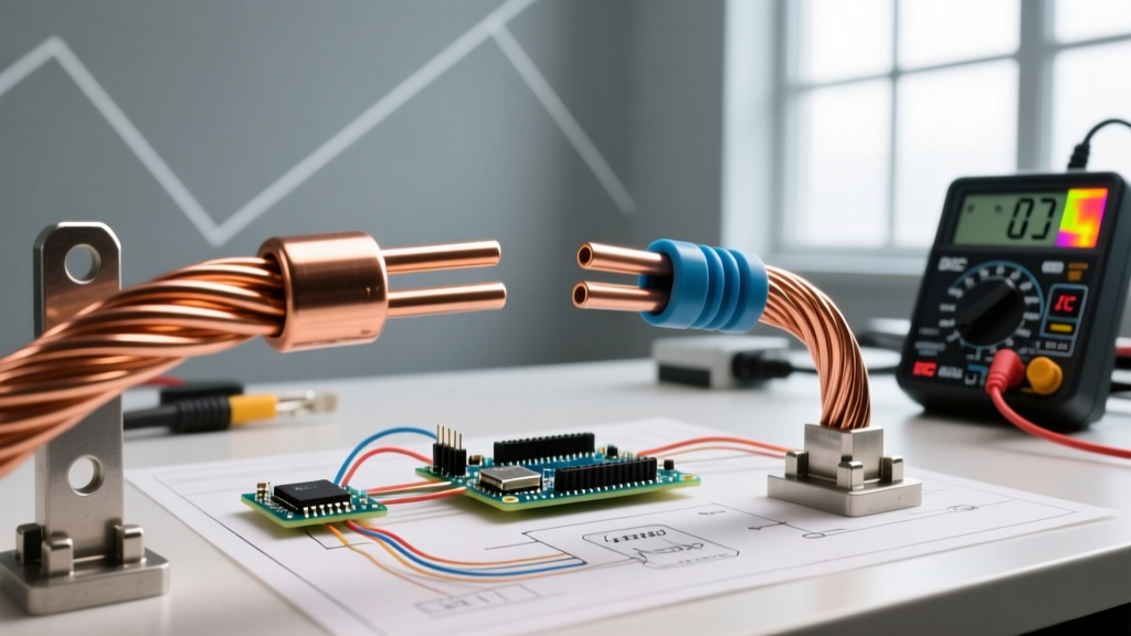
In the realm of electrical DIY, marine wiring, and high-current DC systems, the debate between using a soldered copper connection and a mechanical crimp is one of the most fiercely contested topics. Both methods create an electrically conductive path, but their metallurgical and mechanical behaviors under stress, heat, and vibration are vastly different. While soldering creates a true alloy bond between the copper strands and the filler metal, crimping relies on extreme mechanical deformation to create a cold-weld gas-tight seal.
Choosing the wrong method can lead to catastrophic failures, ranging from localized voltage drops to electrical fires. This decision framework will help you evaluate your specific application, wire gauge, and environmental factors to determine whether a soldered copper joint or a crimped termination is the superior choice for your project.
The Decision Matrix: When to Solder and When to Crimp
Use the following matrix as a rapid evaluation tool before beginning your termination work. This framework accounts for environmental stressors and wire geometry.
| Application Scenario | Wire Type & Gauge | Environmental Stress | Recommended Method |
|---|---|---|---|
| Marine & Automotive DC | Stranded (18 AWG - 4/0 AWG) | High Vibration, Moisture | Crimping (with adhesive heat shrink) |
| Stationary Solar Battery Banks | Stranded (2/0 AWG - 4/0 AWG) | High Current, Thermal Cycling | Crimping (Hydraulic) or Soldered Lug + Crimp |
| PCB & Electronics Prototyping | Solid/Stranded (22 AWG - 30 AWG) | Low Vibration, Indoor | Soldered Copper |
| High-Frequency RF Coaxial | Coaxial (RG-58, LMR-400) | Signal Integrity Critical | Soldered Copper (Center Pin) + Crimp (Shield) |
| Heavy Machinery Control Panels | Stranded (10 AWG - 4 AWG) | Constant Vibration, Oil | Crimping (Ratcheting Tool) |
Failure Modes: Why Soldered Copper Joints Fail
To make an informed decision, you must understand the specific failure modes inherent to soldered copper wire terminations. Soldering is not inherently flawed, but it is frequently misapplied in environments where mechanical crimping excels.
Capillary Wicking and Stress Risers
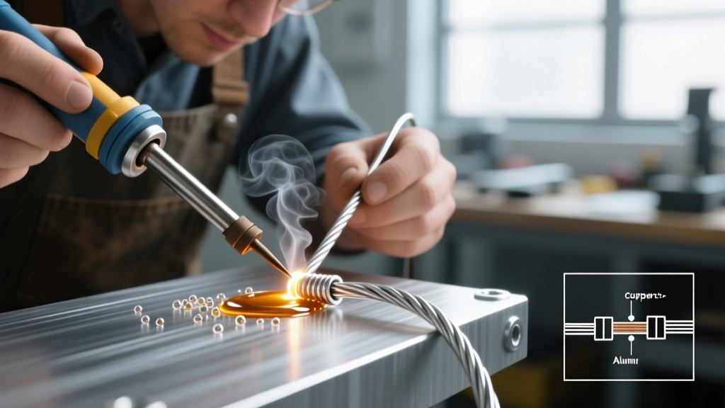
When heat and flux are applied to stranded copper wire, molten solder is drawn up into the wire insulation via capillary action. This phenomenon, known as wicking, transforms a flexible stranded wire into a rigid, solid rod. The exact boundary where the flexible wire meets the rigid, soldered copper creates a severe stress riser. In high-vibration environments (like engine bays or boat hulls), the copper strands will inevitably fatigue and snap precisely at this transition point.
Thermal Fatigue and Creep
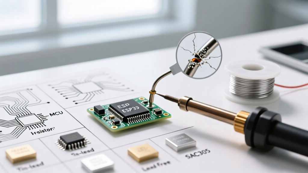
Standard 60/40 (Sn63/Pb37) rosin-core solder melts at 361°F (183°C), but it begins to exhibit creep (slow plastic deformation under mechanical stress) at much lower temperatures. If a soldered copper lug is subjected to high electrical resistance and heats up to 150°F (65°C) under heavy load, the mechanical clamping pressure of a screw terminal can cause the solder to deform, loosening the connection and creating a thermal runaway loop.
Galvanic Corrosion
Solder is an alloy of tin and lead (or tin, silver, and copper in lead-free SAC305 variants). When exposed to moisture and dissimilar metals (like aluminum busbars or zinc-plated steel battery terminals), the soldered copper joint becomes part of a galvanic cell, accelerating corrosion and increasing contact resistance.
Application Scenarios: A Practical Framework
Scenario A: Marine and Automotive (High Vibration)
In mobile applications, vibration is the enemy of soldered copper. The American Boat and Yacht Council (ABYC) standard E-11 explicitly advises against using solder as the sole means of mechanical support for wire terminations. For marine environments, a high-quality ratcheting crimp tool combined with adhesive-lined polyolefin heat shrink is the undisputed gold standard. The crimp provides the mechanical grip and gas-tight electrical seal, while the heat shrink prevents moisture ingress and provides strain relief.
Scenario B: Solar Battery Banks and High-Current DC
For stationary, high-current applications like 48V solar battery banks utilizing 4/0 AWG copper welding cable, the rules shift slightly. While a hydraulic crimp is still preferred, many off-grid builders successfully use soldered copper lugs. However, the correct technique requires a heavy-duty heat source (like a MAP-Pro torch) to quickly melt high-temperature silver-bearing solder (such as Stay-Brite 8) without lingering long enough to melt the heavy-cable insulation. Pro Tip: For maximum reliability in battery banks, use a lug designed for both crimping and soldering: crimp it first to establish the mechanical gas-tight seal, then flow solder into the inspection hole to eliminate any microscopic voids.
Scenario C: Solid Wire and Low-Voltage Electronics
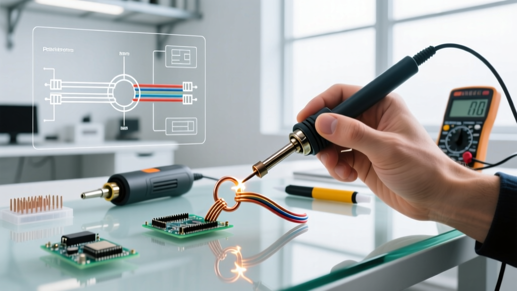
When working with solid copper wire (e.g., 14 AWG THHN in a junction box or 22 AWG hookup wire on a breadboard), soldered copper joints are highly reliable. Solid wire does not suffer from capillary wicking in the same way stranded wire does, and the absence of vibration negates the risk of fatigue failure. For tinning solid wire ends before inserting them into screw terminals, a light coating of Kester 44 rosin-core solder prevents the screw from crushing and deforming the bare copper over time.
Step-by-Step: Executing a Perfect Soldered Copper Lug
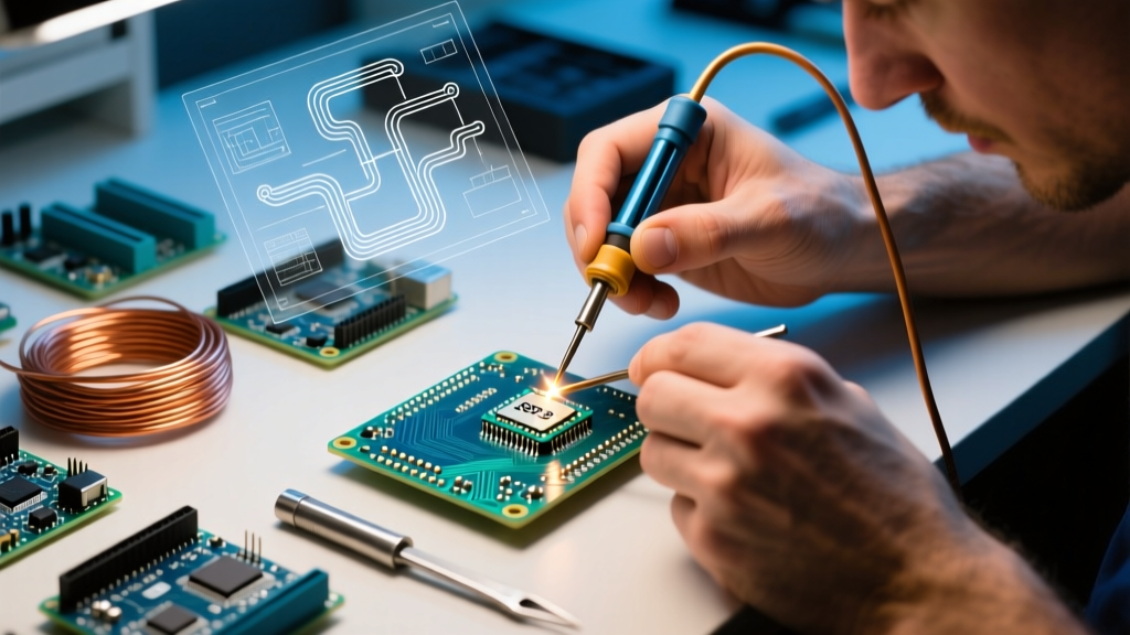
If your decision framework dictates that a soldered copper connection is appropriate for your project, follow these exact steps to ensure a low-resistance, high-integrity joint.
- Preparation: Strip the wire precisely to the depth of the lug barrel plus 1/16th of an inch. Do not nick the copper strands.
- Fluxing: Apply a high-quality, non-corrosive rosin flux (e.g., MG Chemicals 8341) to the bare copper strands. Never use plumbing acid flux on electrical copper.
- Pre-Tinning: Using a high-wattage iron (minimum 100W for 10 AWG; a torch for larger gauges), heat the wire, not the solder. Once the copper reaches the melting point of your alloy, feed the solder in until it wicks just to the edge of the insulation.
- Lug Seating: Insert the pre-tinned wire into the lug barrel. Apply heat to the lug barrel until the pre-applied solder reflows and bonds the wire to the terminal.
- Cooling and Cleaning: Allow the joint to cool naturally. Do not blow on it or quench it in water, as this causes micro-fractures in the solder crystalline structure. Wipe away any excess flux residue with isopropyl alcohol.
- Sealing: Slide a piece of 3:1 shrink ratio, adhesive-lined heat shrink over the joint and apply heat until the adhesive purges slightly from the edges.
2026 Tooling and Material Cost Breakdown
Building a reliable termination kit requires an upfront investment. Below is a realistic look at 2026 pricing for professional-grade electrical termination tools.
- Ratcheting Crimper (Knipex 97 53 14): ~$145. Essential for insulated and non-insulated terminals from 24 to 10 AWG.
- Hydraulic Crimper (TE Connectivity or Generic 12-Ton): $120 - $850. Required for 2 AWG to 4/0 AWG battery lugs.
- Temperature-Controlled Soldering Station (Hakko FX-951): ~$330. Necessary for precise heat control to prevent wicking on smaller gauges.
- MAP-Pro Torch (Bernzomatic TS8000): ~$75. The standard for heavy-gauge soldered copper lugs.
- Solder (Kester 44 Sn63/Pb37, 1lb spool): ~$55. The industry benchmark for electrical soldering.
- Adhesive-Lined Heat Shrink (3M EPS300): ~$35 for a multi-pack. Crucial for environmental sealing.
Industry Standards and Compliance
When designing systems for commercial, aerospace, or strict DIY compliance, your decision between soldering and crimping must align with established industry frameworks. The IPC/WHMA-A-620 standard (Requirements and Acceptance for Cable and Wire Harness Assemblies) provides exhaustive visual criteria for both crimped and soldered copper terminations. It explicitly defines acceptable wicking limits and solder fillet shapes.
Similarly, the NASA Workmanship Standards (NASA-STD-8739.3) dictate that soldered connections must never be used as a substitute for mechanical strain relief. In mission-critical applications, a wire must be mechanically secured (via a crimp or screw) before the soldered copper joint is even considered. By internalizing these standards, DIYers and professionals alike can build electrical systems that are not only functional but fundamentally safe and resilient against the test of time and environment.
Expert Insight: The phrase 'soldered copper' often evokes images of plumbing pipes, but in electrical engineering, it represents a specific metallurgical interface. Treat the solder as an electrical sealant and the crimp as the mechanical anchor. When you separate these two functions in your mind, the decision framework becomes instantly clear.