
The Physics of PCB Rework: Convection vs. Conduction
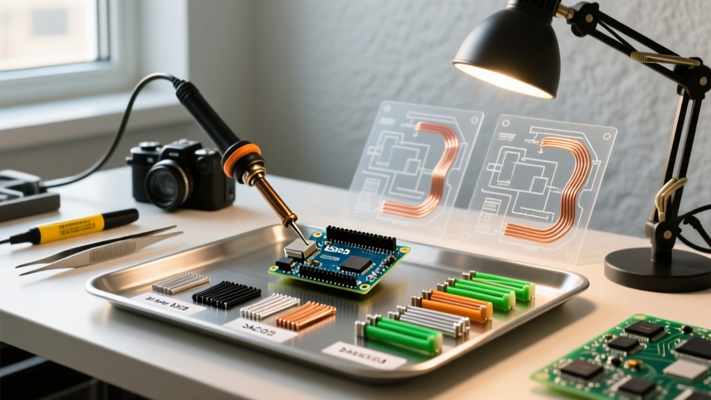
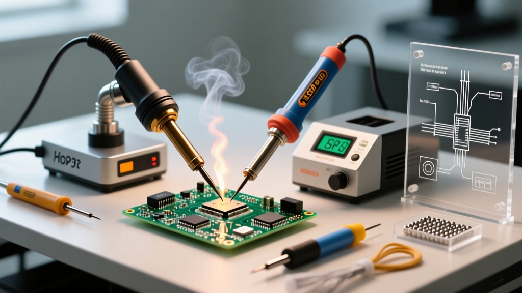
When tackling modern printed circuit board (PCB) repair, technicians face a fundamental thermodynamic choice: convective heating via an air heat gun or conductive heating via a traditional soldering iron. As surface mount device (SMD) components shrink to 0402 (1.0mm x 0.5mm) and ball grid array (BGA) packages hide hundreds of solder joints beneath their silicon bodies, understanding the physics of air heat gun soldering versus direct-contact iron soldering is no longer optional—it is the baseline requirement for successful rework.
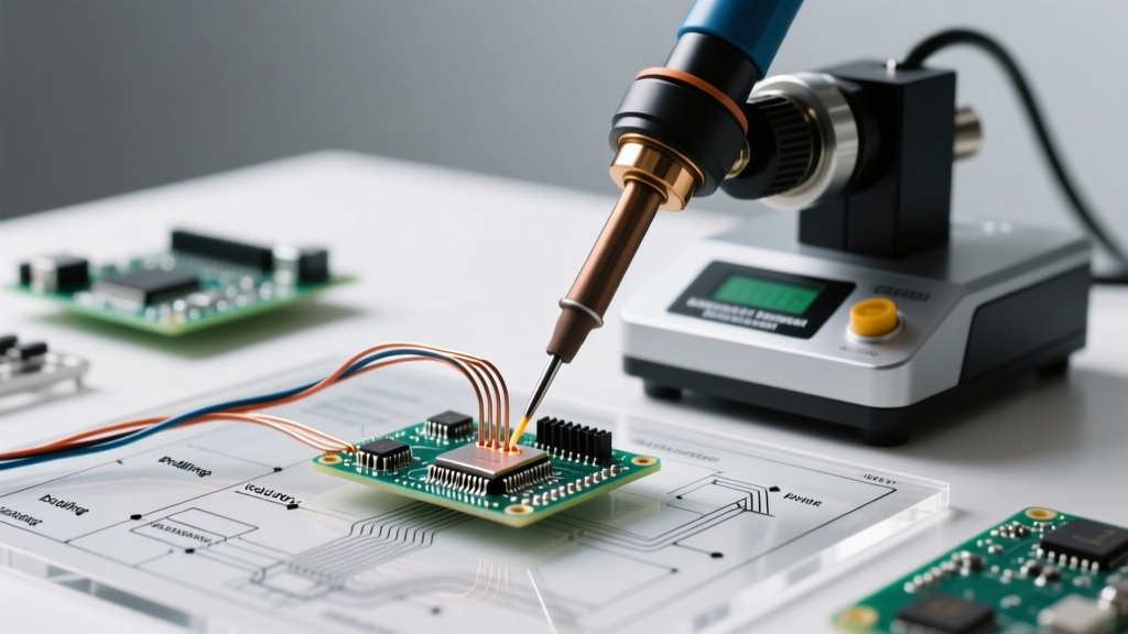
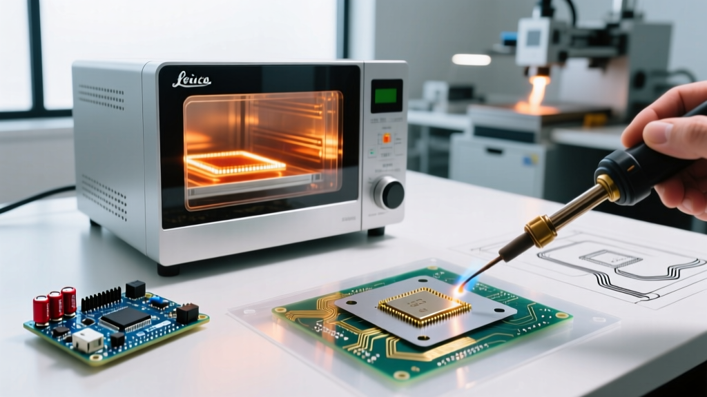
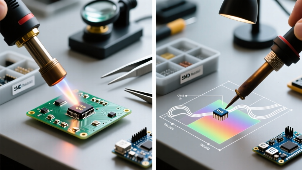
Conductive heating relies on direct physical contact. A copper or iron-clad tip transfers thermal energy directly into the solder joint. This method is exceptionally precise but suffers from 'thermal shadowing,' where large ground planes act as heat sinks, pulling thermal energy away from the joint and causing cold solder defects. Conversely, air heat gun soldering utilizes forced convection. Heated air (typically 100°C to 450°C) is blown across the component, heating the entire package and all underlying pads simultaneously. This eliminates thermal shadowing but introduces fluid dynamic challenges, such as displacing lightweight passives if airflow is improperly calibrated.
2026 Equipment Cost & Capability Matrix
The market for rework stations has matured significantly. Below is a comparison of the industry-standard tools for both methodologies as of 2026, highlighting the investment required for professional-grade results.
| Equipment Type | Model Benchmark | Avg. Price (2026) | Best Application | Thermal Recovery |
|---|---|---|---|---|
| Hot Air Rework Station | Quick 861DW | $260 - $290 | QFN/BGA removal, heat shrink, multi-pin ICs | Moderate (Air mass dependent) |
| Precision Soldering Iron | Hakko FX-951 | $240 - $270 | 0402 passives, SOICs, through-hole, drag soldering | Excellent (Direct sensor) |
| Hybrid/Advanced Station | JBC CD-2BQE | $680 - $750 | High-density interconnect (HDI), micro-BGA | Instantaneous (Cartridge tip) |
Air Heat Gun Soldering: Mastering Convective Rework
Hot air rework is the undisputed king of multi-pin component removal and bottom-termination package installation. However, it requires a nuanced understanding of thermal profiles and airflow dynamics.
Optimal Thermal Profiles for Lead-Free SAC305
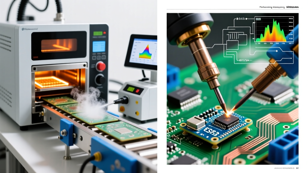
Most modern consumer electronics utilize SAC305 (Sn96.5/Ag3.0/Cu0.5) lead-free solder, which has a liquidus temperature of 217°C to 220°C. To achieve proper wetting without damaging the FR4 substrate (which typically has a glass transition temperature, Tg, of 130°C to 170°C), your air heat gun must deliver a precise thermal curve:
- Preheat Phase: Ramp board temperature to 120°C over 60 seconds to activate flux volatiles and prevent thermal shock.
- Soak Phase: Maintain 150°C - 180°C for 45 seconds to equalize temperature across the component and ground planes.
- Reflow Phase: Spike air temperature to 320°C - 350°C (measured at the nozzle) with an airflow of 20L/min to 30L/min until the solder joints reach 235°C+ and liquefy.
For a deeper dive into foundational SMD techniques, SparkFun's SMD soldering guide provides excellent baseline visual references for flux behavior during these thermal phases.
Critical Failure Modes in Hot Air Rework
Expert Warning: Never apply 350°C hot air directly to a moisture-sensitive QFN or BGA package straight from the antistatic bag. Per IPC/JEDEC J-STD-033 standards, components must be baked at 125°C for 4 to 24 hours depending on their Moisture Sensitivity Level (MSL). Trapped moisture will instantly vaporize, causing the silicon die to crack or delaminate—a catastrophic failure known as the 'popcorn effect.'
Another common failure mode is pad lifting. If the air temperature exceeds 380°C or the dwell time is too long, the copper pads can detach from the FR4 substrate due to Z-axis thermal expansion. Additionally, setting the airflow above 40L/min on a board populated with 0402 resistors will result in the Bernoulli effect lifting and scattering these tiny components across your workbench.
Traditional Iron Soldering: When Conduction Wins
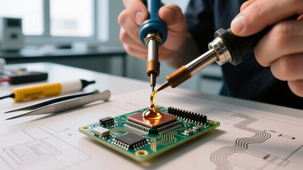
While air heat gun soldering excels at bulk heating, the traditional soldering iron remains irreplaceable for precision work. When installing a single 0603 capacitor or performing drag-soldering on a 0.5mm pitch TQFP (Thin Quad Flat Package), a micro-pencil tip (e.g., Hakko T18-I or JBC C245-116) offers unparalleled control.
The primary limitation of the iron is thermal mass management. If you are soldering a heavy-gauge wire to a large copper pour, a standard 60W iron will stall as the copper acts as an infinite heat sink. In these scenarios, technicians must either increase the tip temperature (risking flux burn-off) or switch to a higher-wattage iron (100W+) to maintain the thermal differential required for rapid wetting. For comprehensive safety and technique protocols, refer to the Adafruit guide to excellent soldering, which outlines proper tip tinning and maintenance to maximize conductive efficiency.
Step-by-Step: Removing a 48-Pin QFP Using an Air Heat Gun
To illustrate the practical application of air heat gun soldering, here is an exact procedure for safely extracting a 48-pin QFP (Quad Flat Package) microcontroller from a populated PCB without damaging adjacent components or the underlying vias.
- Preparation: Apply a generous amount of tacky flux (e.g., Amtech NC-559-V2-TF or Chip Quik SMD291AX) to all four sides of the QFP pins. This lowers the surface tension of the molten solder and prevents bridging during removal.
- Kapton Shielding: Apply high-temperature Kapton tape and aluminum foil to protect surrounding sensitive components (especially electrolytic capacitors and plastic connectors) from convective heat bleed.
- Nozzle Selection: Attach a 14mm or 16mm square nozzle to your Quick 861DW. The square profile matches the QFP footprint, ensuring even heat distribution across all pin rows simultaneously.
- Thermal Application: Set the station to 340°C with an airflow of 25L/min. Hold the nozzle 10mm above the IC. Move in a tight, continuous circular motion to prevent localized overheating of the silicon die.
- Extraction: After approximately 15 to 20 seconds, gently nudge the corner of the IC with fine-point titanium tweezers. If the component shifts freely, the solder has fully liquefied. Lift the IC straight up. Never pull laterally, or you will shear the PCB pads.
- Cleanup: Use a copper desoldering braid (Chemtronics 2mm width) and a flux-cored soldering iron at 350°C to flatten the remaining solder on the pads, preparing the site for the replacement chip.
Expert Verdict: Building a Complete Rework Station
The debate between air heat gun soldering and traditional iron soldering is a false dichotomy; professional PCB rework demands both. The air heat gun is your demolition and heavy-lifting tool, capable of safely removing multi-layer BGAs, QFNs, and heavily grounded connectors that would instantly stall a soldering iron. The traditional iron is your scalpel, used for precision placement, drag soldering, and cleaning up the pads after the hot air has done its job.
For hobbyists and entry-level repair technicians in 2026, allocating $500 to acquire both a reliable hot air station (like the Quick 861DW) and a fast-recovering iron (like the Hakko FX-951) will provide 95% of the capability of a $2,000 JBC setup. Mastering the thermal profiles and fluid dynamics of both methods, while strictly adhering to IPC J-STD-001 standards for workmanship, is the true hallmark of an elite electronics technician.