
The Core Debate: Mechanical Crimp vs. Soldered Ring Terminals
When building custom wiring harnesses, repairing automotive electronics, or terminating high-current DC lines, the termination method dictates the lifespan of your circuit. The visual and metallurgical differences in soldered rings before and after the application of heat and filler metal reveal a complex engineering trade-off. Should you rely solely on a mechanical cold-weld crimp, or should you flow solder into the crimp barrel for added environmental sealing?
To answer this, we must examine the physical states of the connection. According to guidelines referenced by IPC wiring standards, a properly executed crimp creates a gas-tight seal that is theoretically sufficient for conductivity and mechanical retention. However, in harsh environments—such as marine applications or under-hood automotive bays—oxidation remains a persistent threat. Understanding the transition from a raw crimp to a soldered joint is critical for any DIY electrician or electronics hobbyist.
Understanding the "Before" State: The Mechanics of a Crimp
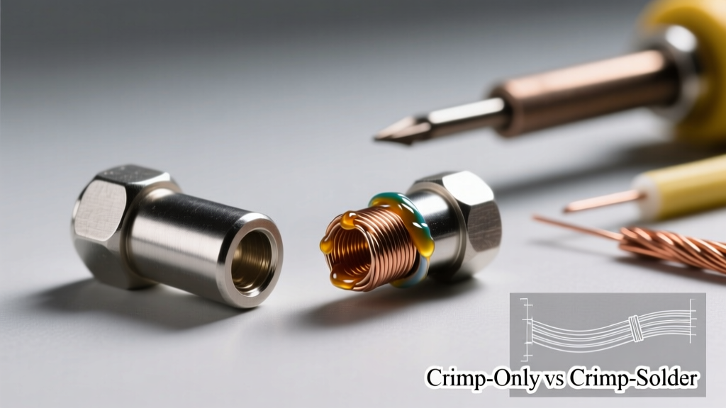
Before solder enters the equation, the ring terminal (such as a TE Connectivity PIDG or Klever nylon-insulated lug) relies entirely on mechanical deformation. When you compress the copper or tin-plated brass barrel around stranded copper wire using a ratcheting crimper, the metal strands are forced into the ridges of the terminal barrel.
- Cold Welding: The immense pressure breaks down surface oxides on both the wire and the terminal, allowing the bare metals to fuse at a molecular level.
- Micro-Voids: Despite a tight crimp, microscopic gaps remain between the circular wire strands. In the "before" state, these voids are filled with air and potentially trapped flux residue from the wire's manufacturing process.
- Flexibility: The stranded wire retains its natural flexibility right up to the edge of the crimp barrel, allowing it to absorb mechanical vibration without fracturing.
The "After" State: What Solder Actually Does to the Joint
When evaluating soldered rings before and after the soldering process, the "after" state represents a fundamental shift in the joint's metallurgical and physical properties. By applying a rosin-based flux and heating the crimped barrel with a high-wattage iron (like the Hakko FX-951 or a Pinecil V2 set to 380°C for SAC305 lead-free solder), capillary action draws the molten alloy into those microscopic voids.
The resulting intermetallic compound (IMC) layer—a thin boundary where tin and copper atoms intermingle—eliminates air pockets. This effectively seals the joint against moisture and oxygen, preventing the dreaded "green crust" (copper oxide) that increases electrical resistance over time. However, this "after" state also introduces rigidity, which brings us to the most critical failure mode in terminal soldering.
Visualizing Soldered Rings Before and After: The Wicking Hazard
Amateurs often judge the "after" state by how much solder they can pack into the terminal. This is a dangerous misconception. According to aerospace workmanship data archived by NASA Electronic Parts and Packaging (NEPP), excessive solder wicking is a primary cause of harness failure in high-vibration environments.
Expert Warning: The Stress Riser Effect
If molten solder wicks up into the stranded wire past the crimp barrel's insulation grip, it transforms a flexible stranded wire into a rigid solid conductor. Under vibration, the wire will bend, but the soldered section will not. This creates a severe stress riser exactly at the boundary where the solder ends, leading to rapid metal fatigue and a snapped wire.
A proper "after" state should feature a smooth, concave solder fillet visible only at the wire entry point of the barrel. The insulation crimp wings must remain completely free of solder to maintain their mechanical grip on the wire jacket, acting as a strain relief.
Head-to-Head Comparison Matrix
Below is a direct comparison of the performance metrics between a crimp-only joint (the "before" state) and a crimp-and-solder joint (the "after" state), based on 10 AWG to 12 AWG copper wire terminations.
| Feature | Crimp-Only (Before Solder) | Crimp-and-Solder (After Solder) |
|---|---|---|
| Tensile Strength | High (Relies on mechanical deformation) | High (Mechanical + IMC metallurgical bond) |
| Vibration Resistance | Excellent (Wire remains flexible) | Poor to Fair (Risk of fatigue if wicking occurs) |
| Corrosion Resistance | Fair (Micro-voids allow moisture ingress) | Excellent (Solder displaces air and seals strands) |
| Electrical Resistance | Very Low (<0.001 Ω for 10 AWG) | Extremely Low (Solder fills all micro-gaps) |
| Execution Time | ~5 seconds per termination | ~25 seconds per termination |
| Tooling Cost (2026) | $45 - $120 (Ratcheting crimper) | $150 - $250 (Crimper + 70W+ Soldering Station) |
Step-by-Step: Achieving the Perfect Crimp-and-Solder Joint
If your application demands the environmental sealing of a soldered joint—such as marine battery lugs or outdoor solar combiner boxes—follow this precise methodology to avoid the pitfalls of the "after" state.
Required Tools & Materials
- Terminals: TE Connectivity PIDG or AMP commercial ring terminals (As of early 2026, a bulk box of 100 12-10 AWG terminals costs roughly $38 from authorized distributors like TE Connectivity or Mouser).
- Crimper: Knipex 97 49 61 or a high-quality ratcheting equivalent with the correct die for the wire gauge.
- Solder: Kester 245 (63/37 Sn/Pb eutectic) for DIY/automotive due to its 183°C melting point and superior wetting. Use SAC305 (Sn96.5/Ag3.0/Cu0.5) if RoHS compliance is required.
- Flux: Kester 186 RMA (Rosin Mildly Activated) liquid or paste. Never use acid-core plumbing flux on electrical ring terminals.
- Heat Source: A temperature-controlled station (e.g., Weller WE1010 or Hakko FX-888D) equipped with a wide chisel tip (minimum 4mm width) for rapid thermal transfer.
Execution Sequence
- Precision Stripping: Strip the wire insulation so that the bare strands extend exactly to the end of the terminal's wire barrel. Do not leave excess bare wire exposed between the insulation grip and the wire crimp.
- The Mechanical Crimp: Insert the wire fully. Use the ratcheting crimper to compress the wire barrel and the insulation grip simultaneously. Verify the crimp by attempting to pull the wire out; it should withstand at least 40 lbs of pull-force for 12 AWG.
- Flux Application: Apply a micro-drop of RMA flux to the wire entry point of the barrel. The flux is mandatory; it reduces surface tension and allows the solder to wick inward rather than balling up on the outside.
- Thermal Transfer: Apply the pre-tinned chisel tip to the bottom of the terminal barrel (opposite the wire entry) and the wire simultaneously. Heat until the flux sizzles (approx. 2-3 seconds).
- Solder Feeding: Touch the solder wire to the junction where the wire enters the barrel. Capillary action will draw the solder into the barrel. Stop feeding the moment you see a shiny, concave fillet form at the entry point. Do not pack the barrel from the top down.
- Environmental Sealing: Once cooled, slide a 3:1 adhesive-lined dual-wall heat shrink tube over the terminal and apply heat. The inner meltable adhesive layer will seal the soldered joint from moisture ingress.
When to Solder and When to Stick to Crimping
The decision to transition from the "before" crimped state to the "after" soldered state should be dictated by the operating environment, not by habit.
Stick to Crimp-Only When:
- Wiring harnesses in high-vibration environments (motorcycles, engine bays, aerospace).
- High-current AC mains wiring where thermal cycling could cause solder to soften or creep.
- Using pre-insulated, heat-shrink sealed crimp terminals where the shrink tube already provides the environmental barrier.
Opt for Crimp-and-Solder When:
- Marine and boating applications exposed to saltwater and high humidity.
- Stationary DC battery banks and solar arrays where corrosion is the primary enemy.
- Low-voltage, high-current DC connections (like 3D printer heated beds) where minimizing micro-ohm resistance is critical to prevent voltage drop.
Frequently Asked Questions (FAQ)
Can I solder a ring terminal without crimping it first?
No. This is a severe safety hazard. Solder is a soft metal with poor tensile strength. If the wire is pulled, the solder will easily tear or deform, breaking the connection. The mechanical crimp must always bear the physical load; the solder should only provide conductivity and sealing.
Why does my soldered ring terminal look dull and grainy?
A dull, grainy appearance in the "after" state indicates a cold joint or a disturbed joint. This happens if the wire was moved while the solder was cooling through its plastic range, or if your iron lacked the thermal mass to heat the thick copper terminal barrel adequately. Upgrade to a 70W+ station and use a wider chisel tip.
Does soldering ring terminals increase the current rating?
No. The current rating is dictated by the cross-sectional area of the copper wire and the terminal's contact surface with the busbar or stud. Soldering simply ensures that the joint's resistance remains stable over time by preventing oxidation, but it does not increase the baseline ampacity of the wire.