
Navigating the Soldering Reflow Process: From Prototype to Production
Transitioning from hand-soldering through-hole components to assembling surface-mount technology (SMT) requires a fundamental shift in thermal management. The soldering reflow process is not merely about melting solder; it is a precisely orchestrated thermal profile designed to activate flux, evaporate solvents, form a reliable intermetallic compound (IMC) layer, and cool without inducing mechanical stress.
Whether you are assembling a single IoT prototype or running a 500-unit batch of medical sensors, selecting the wrong reflow method will result in catastrophic yields, tombstoning, or latent cold joints. This decision framework provides a structured approach to selecting the right reflow equipment and methodology based on your specific production volume, budget, and component density.
The Physics of the Profile: Understanding the 4 Stages
Before evaluating equipment, you must understand the universal thermal profile required for modern lead-free assemblies (typically SAC305: Sn96.5/Ag3.0/Cu0.5). According to industry guidelines and IPC-A-610 standards, a successful reflow profile consists of four distinct phases:
- Preheat (Ramp): Temperature rises from ambient to ~150°C. The ramp rate must be strictly controlled between 1°C/s and 3°C/s. Ramping too fast causes volatile flux solvents to boil and explode, resulting in solder balling.
- Thermal Soak: The board dwells between 150°C and 200°C for 60 to 120 seconds. This allows the entire PCB thermal mass to equalize and activates the flux to remove surface oxides.
- Reflow (Liquidus): The temperature crosses the liquidus line (217°C for SAC305) and peaks at 235°C–245°C. Time above liquidus (TAL) should be kept between 45 and 90 seconds to ensure proper IMC formation without damaging silicon dies.
- Cooling: A controlled descent (typically 2°C/s to 4°C/s) to prevent thermal shock to ceramic capacitors and ensure a fine-grain, mechanically strong solder joint.
Decision Matrix: Matching Equipment to Production Scale
Use the following framework to determine which tier of reflow equipment aligns with your operational requirements.
| Production Tier | Weekly Volume | Optimal Equipment | Est. Budget | Best For |
|---|---|---|---|---|
| Tier 1: Hobby / R&D | 1 - 10 boards | PID-Controlled Hotplate / Smart Heater | $70 - $150 | Simple 2-layer boards, large pitch ICs |
| Tier 2: Advanced Proto | 10 - 50 boards | Hot Air Rework Station + Preheater | $300 - $600 | Mixed tech, BGA rework, dense 4-layer boards |
| Tier 3: Small Batch | 50 - 500 boards | Benchtop Reflow Oven (Conveyor/Drawer) | $2,500 - $6,000 | Repeatable production, 0201 passives, QFNs |
Tier 1: The Budget Tier (Hotplates and Smart Heaters)
For low-volume prototyping where budget is the primary constraint, bottom-up heating via a hotplate is highly effective, provided you have closed-loop temperature control.
Equipment Spotlight: Miniware MHP30 & DIY PID Setups
The Miniware MHP30 (~$69) is a 100W smart heating platform with an integrated thermocouple and programmable thermal profiles. It is exceptional for boards smaller than 50x50mm. For larger boards, the standard approach is pairing an 800W resistive hotplate (~$40) with an Inkbird ITC-308 PID controller (~$35) and a K-type thermocouple.
Expert Insight: Hotplates only heat the bottom of the PCB. If you are using a 4-layer board with heavy internal copper pours, the thermal mass will create a massive temperature delta between the bottom and top layers. Always use a preheater or hot air gun from the top to assist the final reflow stage on complex multilayer boards.
Tier 2: The Precision Tier (Hot Air & Preheaters)
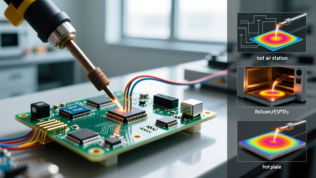
When your designs incorporate fine-pitch QFNs, BGAs, or dense ground planes that act as heat sinks, a hot air rework station paired with a bottom preheater becomes mandatory. This allows you to manually execute the soldering reflow process with localized precision.
Equipment Spotlight: Quick 861DW
The Quick 861DW (priced between $250 and $280) remains the undisputed king of the prototyping bench in 2026. Its 1000W heating element and brushless fan provide immediate thermal recovery, a critical factor when blowing air across a board with high thermal mass.
When using hot air for full-board reflow, technique is paramount. As detailed in comprehensive hot air rework guides, you must keep the nozzle moving in a continuous circular pattern at a distance of 1 to 2 inches. Set the temperature to 350°C and airflow to 40-50%. The air cools significantly between the nozzle and the board; the 350°C setting ensures the board surface reaches the required 235°C peak without scorching the FR4 substrate.
Tier 3: The Production Tier (Benchtop Reflow Ovens)
Once you cross the threshold of 50 boards per week, manual hot air or hotplate methods become a bottleneck and introduce unacceptable human-error variance. Benchtop reflow ovens automate the entire soldering reflow process, ensuring every board experiences the exact same thermal profile.
Equipment Spotlight: NeoDen IN12 & Whizzer T-8
For small-to-medium enterprises, the NeoDen IN12 (~$2,800) is a heavy-duty benchtop oven featuring internal heating zones and a motorized conveyor. Unlike drawer-style ovens (which require you to manually open the door to drop the temperature for the cooling phase), conveyor ovens pull the board through distinct physical heating and cooling zones, perfectly mimicking industrial inline ovens.
For those with tighter bench space, the Whizzer T-8 (~$1,200) offers a drawer-style mechanism with 8 distinct heating zones. While drawer ovens require careful timing to execute the cooling ramp, modern firmware allows for programmable auto-eject features to initiate cooling at the exact right second.
Failure Mode Analysis & Troubleshooting
Even with the right equipment, improper profile tuning leads to distinct failure modes. Cross-referencing your physical defects with NASA workmanship standards for soldering can help diagnose the root cause.
- Tombstoning (Drawbridging): One end of a passive component lifts off the pad. Root Cause: Uneven heating across the component. One pad reaches liquidus before the other, and the surface tension of the molten solder pulls the component upright. Fix: Extend the thermal soak phase to ensure the entire board equalizes before crossing the 217°C threshold. Check PCB pad geometry for asymmetrical thermal relief connections.
- Solder Balling / Splattering: Tiny spheres of solder trapped under components or on adjacent pads. Root Cause: The preheat ramp rate is too aggressive (>3°C/s). The flux solvents boil violently and eject molten solder. Fix: Reduce the ramp rate and ensure your solder paste has not absorbed excess ambient moisture (always store paste in a refrigerated environment and allow it to reach room temperature before printing).
- Cold Joints / Dull Grainy Finish: The solder joint lacks a smooth, shiny fillet and exhibits high electrical resistance. Root Cause: Insufficient peak temperature or inadequate Time Above Liquidus (TAL). The IMC layer failed to form properly. Fix: Increase peak temperature by 5°C-10°C and verify thermocouple placement to ensure you are reading the actual board temperature, not just the oven's ambient air temperature.
- Voiding in BGAs/QFNs: X-ray inspection reveals large air pockets inside the solder joint. Root Cause: Flux outgassing is trapped beneath the component body during the liquidus phase. Fix: Switch to a no-clean solder paste with lower outgassing characteristics, or implement a vacuum reflow process if voiding must remain below 5%.
Final Verdict: Scaling Your Assembly Line
The ideal soldering reflow process is dictated entirely by your yield requirements and component density. If you are blinking up a weekend 555-timer circuit, a $70 MHP30 hotplate is more than sufficient. However, if you are designing a 6-layer RF board packed with 0201 decoupling capacitors and BGA microcontrollers, investing in a Quick 861DW hot air station or stepping directly into a NeoDen IN12 benchtop oven is not a luxury—it is a strict requirement for functional hardware. Map your volume, respect the thermal soak, and let the physics of the profile dictate your equipment purchases.