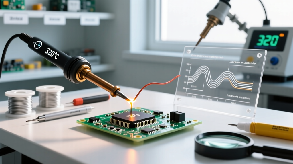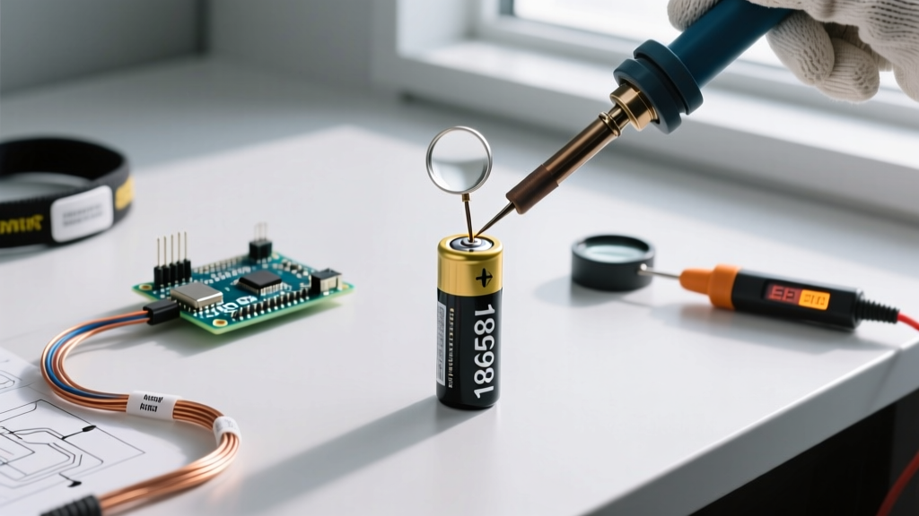

The Soldering a Battery Dilemma: Heat vs. Connection
In the electronics community, a pervasive dogma exists: never solder directly to a battery terminal. Purists argue that the heat required to wet a nickel-plated steel can or an aluminum pouch tab will inevitably degrade the cell chemistry, melt the internal separator, or trigger the Current Interrupt Device (CID). However, in DIY electronics, rapid prototyping, and field repairs, soldering a battery is often an unavoidable necessity. The reality is that when executed with strict thermal management and the correct metallurgical approach, soldering can yield a joint with lower electrical resistance and higher mechanical shear strength than a poorly calibrated spot weld.
As of 2026, with the proliferation of high-wattage smart irons and advanced no-clean fluxes, the barrier to safe, reliable battery soldering has lowered significantly. This decision framework will guide you through the chemistry, equipment selection, and execution protocols required to solder a battery safely without inducing thermal runaway or permanent cell death.
The Core Decision Matrix: Soldering vs. Alternatives
Before firing up your iron, you must evaluate whether direct soldering is actually the optimal path for your specific build. Use the matrix below to determine the best connection methodology based on your production volume, budget, and risk tolerance.
| Connection Method | Setup Cost (2026) | Thermal Risk | Joint Resistance | Ideal Application |
|---|---|---|---|---|
| Direct Soldering | $30 - $250 | High (if unskilled) | Very Low (<5 mΩ) | Prototyping, one-off repairs, heavy-gauge wire RC builds |
| Spot Welding | $150 - $800+ | Minimal | Low (5-15 mΩ) | High-volume 18650/21700 battery pack assembly |
| Mechanical Holders | $2 - $15 per pack | Zero | High (20-50+ mΩ) | Low-drain IoT devices, consumer electronics, swappable builds |
| Pre-Tabbed Cells | + $0.50/cell premium | Zero (to cell) | Low | Professional manufacturing, LiPo pouch integrations |
Phase 1: Cell Chemistry & Form Factor Assessment
Not all cells react to heat equally. The physical construction of the battery dictates your thermal budget.
Cylindrical Cells (18650, 21700, 4680)
The positive and negative terminals of standard Li-ion cylindrical cells are typically nickel-plated steel. Steel is notoriously difficult to wet with solder. It requires aggressive flux and high thermal mass. The primary risk here is heat traveling down the steel can and boiling the liquid electrolyte. The internal CID (Current Interrupt Device) on the positive terminal is designed to snap and permanently disconnect the cell if internal pressure rises due to temperatures exceeding roughly 105°C (221°F).
Pouch Cells (LiPo, LiFePO4)
Pouch cells feature protruding tabs—usually aluminum for the cathode and copper/nickel for the anode. Aluminum is exceptionally difficult to solder without specialized ultrasonic irons or aggressive acid fluxes (which cause corrosion). Furthermore, the polymer seal at the base of the tab melts at relatively low temperatures. If you must solder a LiPo tab, you must use a heavy aluminum heat-sink clip between the solder joint and the pouch body to wick heat away from the seal.
NiMH and NiCd Cells
Nickel-metal hydride cells are generally more forgiving of heat than Li-ion, but they still possess pressure relief vents on the positive terminal. Excessive heat can deform the plastic gasket sealing the vent, leading to slow electrolyte leaks and eventual cell failure.
Phase 2: Equipment Selection for High Thermal Mass
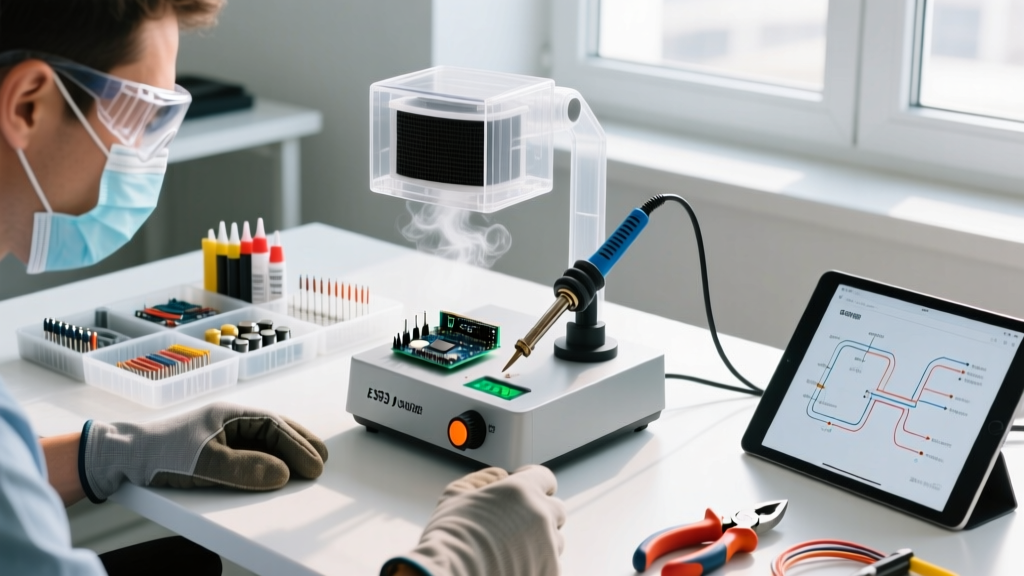
The most common mistake when soldering a battery is using an underpowered iron. A standard 40W ceramic heater iron will suffer from severe thermal droop when it touches the massive heat sink of a battery terminal. To compensate, the user applies the iron for 10+ seconds, slowly cooking the cell. You need an iron that can dump heat instantly and recover in under a second.
The Iron & Tip Matrix
- Weller WE1010NA (70W): A workhorse for bench work. Pair it with the ETA 0.8mm chisel tip or the heavier RT4 1.6mm chisel. The heavy chisel provides the thermal mass necessary to wet steel instantly. (Approx. $140).
- Hakko FX-951 (70W): Utilizes T12 cartridge tips where the heater is embedded directly in the tip. Use the T12-D24 (2.4mm chisel) for optimal heat transfer to 18650 terminals. (Approx. $280).
- Pinecil V2 (65W): The premier budget smart iron. Running on a 24V DC supply, it drives the TS-C4 wide chisel tip with surprising thermal authority, making it ideal for field repairs. (Approx. $28).
Solder Alloy & Flux Selection
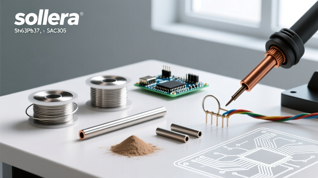
When soldering a battery, 63/37 Sn/Pb (Tin/Lead) eutectic solder is vastly superior to lead-free alternatives like SAC305. Eutectic solder melts sharply at 183°C (361°F) and transitions instantly from liquid to solid. Lead-free solder melts around 217°C–220°C and has a plasticity phase, requiring higher iron temperatures and longer dwell times, which increases the risk of thermal damage to the cell. Use a high-quality 2% to 3% rosin-core wire (e.g., Kester 44 or MG Chemicals 4900P).
For the battery terminal itself, supplement the rosin core with an external no-clean, mildly activated flux gel like Amtech NC-559-V2-TF or MG Chemicals 8341. This breaks down the nickel oxide layer on the steel can without leaving corrosive residues.
Phase 3: The 3-Second Execution Protocol
Follow this strict chronological protocol to ensure the internal temperature of the cell never breaches the 60°C (140°F) degradation threshold.
- Surface Preparation: Lightly scuff the battery terminal with 400-grit sandpaper or a fiberglass scratch pen to remove the factory oxidation layer. Wipe with 99% isopropyl alcohol.
- Pre-Tinning (The Secret Step): Apply a small dab of flux to the scuffed terminal. Touch your 380°C (716°F) chisel tip to the terminal with a dab of solder on the tip. The terminal should wet and form a silver puddle in under 1.5 seconds. Remove the iron and let it cool. Do the same for your wire.
- The Mating Joint: Place the pre-tinned wire onto the pre-tinned battery pad. Apply flux to the junction. Touch the iron to the wire (not the battery pad directly) to transfer heat through the wire into the pad. The solder should reflow in 1 to 2 seconds.
- Thermal Quenching: Remove the iron and immediately blow on the joint or apply a brief puff of compressed air to snap the solder into its solid state, halting heat conduction into the cell body.
CRITICAL WARNING: Never solder both the positive and negative terminals of a bare cell in the same continuous session. Solder the first terminal, wait 5 minutes for the cell to return to ambient room temperature, and then solder the second. According to OSHA guidelines on lithium battery safety, cumulative thermal stress is a primary catalyst for internal separator failure and subsequent thermal runaway.
Failure Modes & Edge Cases
Understanding how joints fail is crucial for quality control in custom battery packs.
- Cold Joints on Steel: If your iron lacks thermal mass, the solder will ball up and roll off the nickel-plated steel. Forcing it with prolonged heat will trip the CID. If the solder doesn't wet in 2 seconds, stop, clean, add more flux, and use a wider chisel tip.
- Shrink Wrap Melting: The PVC heat-shrink sleeve on an 18650 cell begins to deform at around 85°C. If your solder joint is too close to the edge of the terminal, the heat will wick radially and melt the sleeve, exposing the bare steel can. This creates a severe short-circuit hazard when the cell is placed in a metal enclosure or adjacent to other cells. Always leave a 2mm margin from the edge.
- Flux Corrosion: If you use plumbing acid flux or highly activated rosin (RA) to force the solder to wet the steel, the residual acids will eat through the nickel plating over 6 to 12 months, leading to high-resistance joints and potential open circuits. Always use No-Clean (NC) or Rosin Mildly Activated (RMA) fluxes.
Regulatory & Safety Context
While soldering a battery is standard practice in the DIY and repair communities, it is generally frowned upon in mass-manufacturing environments. Organizations like UL (Underwriters Laboratories) heavily scrutinize direct soldering to cell terminals in consumer products due to the difficulty of automated quality control and the risk of latent thermal damage. If you are building a commercial product intended for UL or CE certification, you must transition to automated spot welding or use pre-tabbed cells. However, for bespoke engineering, robotics, and repair, mastering the thermal dynamics of the soldering iron remains an indispensable skill.
Frequently Asked Questions
Can I use a butane soldering iron to solder a battery?
No. Butane irons (like the Portasol) lack precise temperature control and deliver massive, unregulated thermal spikes. The risk of localized overheating and venting the cell is exceptionally high. Stick to temperature-controlled electric or DC smart irons.
Why did my 18650 cell read 0V after soldering?
You tripped the Current Interrupt Device (CID). The heat from your iron caused the internal electrolyte to expand, raising the pressure until the safety disc snapped. The cell is permanently dead and must be recycled safely.
Is it safe to solder wires to a LiPo pouch cell tab?
Only if the tab is exceptionally long and you use an aluminum heat-sink clip between the solder joint and the pouch seal. If the heat reaches the polymer seal, the pouch will delaminate, allowing moisture to enter and destroy the cell chemistry.