
The Baseline Soldering Process Steps (IPC Standard)
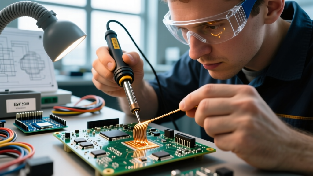
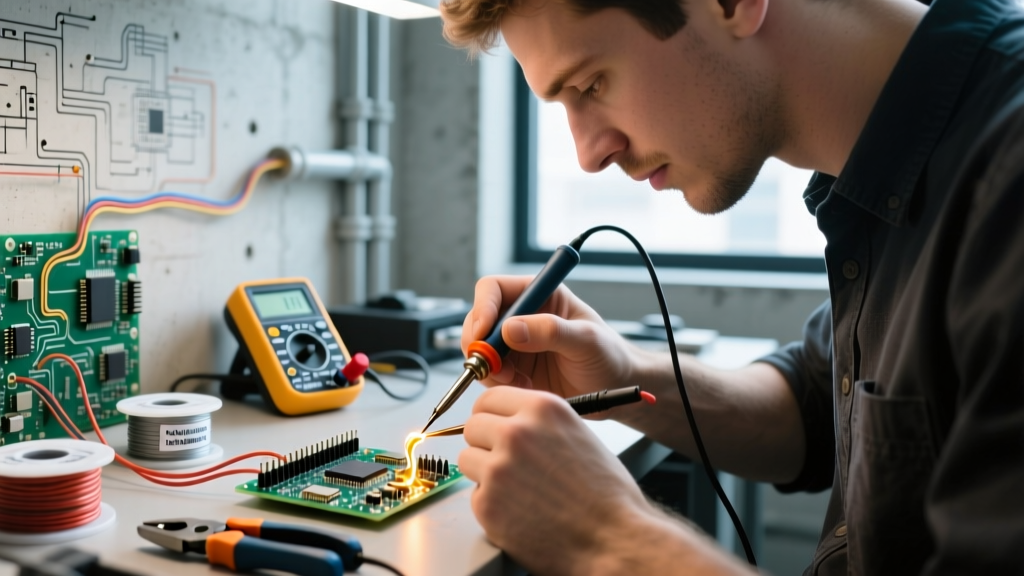
Before adapting your technique for exotic or difficult materials, you must master the baseline soldering process steps as defined by industry standards like IPC J-STD-001. Whether you are using a $120 Weller WE1010NA or a $350 PACE ADS200, the fundamental metallurgical sequence remains constant for standard copper-to-copper or copper-to-FRP4 PCB joints:
- Surface Preparation: Mechanical or chemical removal of bulk oxidation.
- Thermal Pre-conditioning: Bringing the pad and lead to the flux activation temperature (typically 150°C - 180°C).
- Flux Application & Activation: Allowing the flux to dissolve microscopic oxides and lower the surface tension of the molten alloy.
- Heat & Solder Delivery: Applying the solder wire to the joint (not the iron tip) while maintaining a tip temperature 40°C-60°C above the alloy's liquidus point.
- Intermetallic Compound (IMC) Formation: Holding the heat for 1.5 to 3.0 seconds to allow the copper-tin IMC layer to grow to an optimal 1-3 microns.
- Controlled Solidification: Removing heat and allowing the joint to cool without mechanical disturbance.
However, when you introduce materials like stainless steel, aluminum, or heavy nickel plating, these standard soldering process steps will fail. The oxide layers on these metals are either too thermally stable or reform too quickly for standard rosin-based fluxes to penetrate.
Material Compatibility Matrix
Use this matrix to adjust your consumables and thermal profiles before beginning your soldering process steps. Pricing reflects average 2026 market rates for professional-grade materials.
| Base Material | Recommended Flux Chemistry | Optimal Solder Alloy | Iron Tip Temp | Max Dwell Time | Approx. Cost |
|---|---|---|---|---|---|
| Copper / Bare PCB | Rosin Mildly Activated (RMA) | SAC305 (Lead-Free) | 340°C - 360°C | 3.0 seconds | $12 / 2oz |
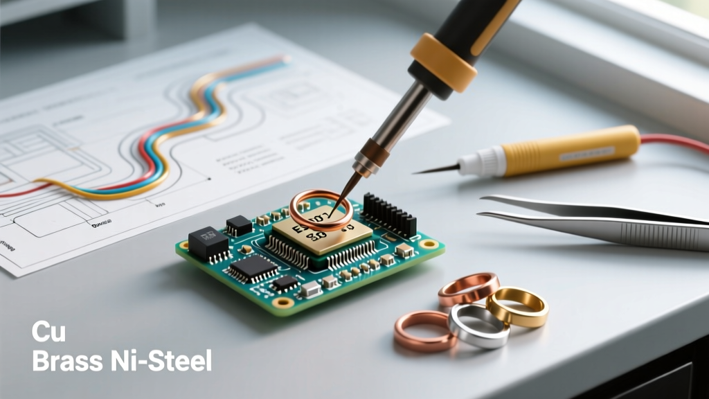
| Stainless Steel | Inorganic Acid (Zinc Chloride) | Sn63/Pb37 or Sn96.5/Ag3.0/Cu0.5 | 380°C - 410°C | 4.0 seconds | $18 / 2oz |
| Aluminum | Specialized Organic Acid (e.g., Alusol) | Indalloy 158 (Sn95/Zn5) | 350°C - 370°C | 5.0 seconds | $45 / 1lb |
| Gold-Plated Terminals | No-Clean or RMA | Sn62/Pb36/Ag2 (Silver-bearing) | 320°C - 340°C | 1.5 seconds | $15 / 2oz |
| Nickel-Plated Connectors | High-Solids Organic Acid (OA) | SAC305 or Sn95/Sb5 | 360°C - 380°C | 3.5 seconds | $22 / 2oz |
Modifying Soldering Process Steps for Difficult Alloys
To achieve reliable metallurgical bonds on non-standard materials, you must alter specific phases of the standard procedure. Here is how to adapt your workflow based on material science principles.
Stainless Steel & High-Carbon Alloys
Stainless steel owes its corrosion resistance to a passive chromium oxide layer. Standard RMA or No-Clean fluxes cannot break down chromium oxide at typical soldering temperatures. According to metallurgical guidelines outlined in the NASA Soldering Handbook (NASA-HDBK-8739.3), joining stainless steel requires highly active inorganic acid (IA) fluxes, such as zinc chloride or ammonium chloride solutions (e.g., Superior Flux No. 30).
Step Modification: You must insert a post-soldering cleaning step. Unlike no-clean fluxes, zinc chloride residues are highly corrosive and electrically conductive. After the joint solidifies, you must scrub the area with hot distilled water and a stiff brush, followed by an isopropyl alcohol (IPA) rinse to prevent rapid galvanic corrosion.
Aluminum-to-Copper Transitions
Aluminum oxide (Al2O3) reforms within milliseconds of being exposed to oxygen, even under a pool of molten flux. To solder aluminum, the standard soldering process steps must be augmented with mechanical action. You must use a specialized flux like Alusol and an alloy specifically designed for aluminum wetting, such as Indium Corporation's Indalloy 158 (95% Tin, 5% Zinc).
Step Modification: During the 'Heat & Solder Delivery' step, use the solder wire itself or a specialized titanium-coated tip to gently abrade the aluminum surface through the liquid flux pool. This mechanical scraping displaces the oxygen, allowing the flux to cap the bare aluminum instantly before a new oxide layer can form.
Gold and Nickel-Plated Terminals
Soldering to gold presents a unique metallurgical hazard: gold leaching. Tin has a high affinity for gold and will dissolve the plating into the solder joint, forming a brittle gold-tin intermetallic compound (AuSn4). This results in catastrophic joint failure under thermal cycling or mechanical shock.
Step Modification: Limit your dwell time strictly to under 1.5 seconds. Additionally, utilize a silver-bearing solder alloy (like Sn62/Pb36/Ag2). The silver in the solder acts as a sacrificial buffer, satisfying the tin's affinity for precious metals and slowing the dissolution of the gold plating into the joint matrix.
Expert Callout: The Pre-Tinning Bridge
When joining two vastly different materials (e.g., a heavy copper ground plane to a thin stainless steel shield), do not attempt to solder them simultaneously. Modify your steps to include a 'pre-tinning' phase. Pre-tin the difficult material (stainless steel) with aggressive flux and a high-temperature iron, clean it, and then use standard RMA flux and a lower-temperature iron to join the pre-tinned surface to the copper. This prevents thermal damage to the PCB while ensuring a solid bond.
Thermal Mass Adjustments & Pre-Heating
Material compatibility isn't just about chemistry; it's about thermal conductivity. If your soldering process steps involve attaching a small wire to a massive copper chassis or a multi-layer PCB with heavy internal ground planes, the base material will act as a massive heat sink. Your soldering iron will drop below the liquidus temperature of the alloy, resulting in a cold, grainy joint.
To solve this, integrate a Thermal Pre-conditioning Step using a dedicated pre-heater. Devices like the PACE PH-100 or Hakko FR-830 (priced between $300 and $600 in 2026) elevate the ambient temperature of the entire assembly to 120°C - 150°C. This reduces the thermal delta your iron must overcome, allowing you to use smaller, sharper tips (like a Hakko T18-B2) without stalling the thermal recovery of the heating element.
Troubleshooting Material-Specific Failure Modes
Even with perfect technique, material incompatibilities manifest in distinct visual defects. Use this diagnostic list to identify where your soldering process steps broke down:
- Dewetting (Nickel/Gold): The solder initially wets the pad but then pulls back into a ball, leaving a thin, irregular film. Cause: The iron was left on the joint too long, burning out the flux and causing the underlying nickel to oxidize, or the gold plating was too thin and fully dissolved. Fix: Reduce dwell time and verify plating thickness.
- Non-Wetting (Aluminum/Stainless): The solder refuses to adhere to the base metal at all, rolling off like water on wax. Cause: Insufficient flux activity to break the specific metal oxide, or the iron tip temperature was too low to activate the specialized flux. Fix: Switch to a higher-activity organic or inorganic acid flux and increase tip temperature by 30°C.
- Grainy/Disturbed Joints (High-Mass Copper): The solder solidifies with a rough, crystalline appearance. Cause: The joint was disturbed during the plastic (mushy) phase of solidification, or the thermal mass of the material caused the solder to cool too slowly while the operator moved the wire. Fix: Implement a pre-heating step and use a higher-wattage iron (e.g., 150W+) for faster thermal recovery.
- Charred PCB Substrate (Mixed Materials): The FR4 fiberglass turns brown or delaminates around the pad. Cause: Applying excessive heat to force a bond on a difficult-to-wet component lead without pre-tinning. Fix: Pre-tin the difficult lead off-board, clean it, and then perform the final assembly at standard PCB temperatures (340°C).
Expert FAQ
Can I use standard plumbing solder for electrical electronics?
No. Plumbing solder often contains high levels of antimony or relies on highly corrosive acid-core fluxes designed for copper pipes. If used in electronics, the acid residue will cause dendritic growth and short circuits within weeks. Always use rosin-core or no-clean electronic-grade solder wire.
How do I safely clean zinc chloride flux off a stainless steel joint?
Zinc chloride is water-soluble but requires aggressive mechanical action. Use a fiberglass scratch brush under running hot distilled water, followed by a neutralizing rinse with a mild baking soda solution, and a final rinse with 99% IPA to displace the water and prevent flash rusting.
Why does my solder joint on a nickel-plated connector look dull and cracked?
Nickel requires higher activation energy than copper. If your iron temperature is too low (below 350°C), the flux cannot clear the nickel oxide, leading to a marginal bond that cracks as it cools due to differing coefficients of thermal expansion (CTE). Increase your temperature and use a high-solids OA flux.