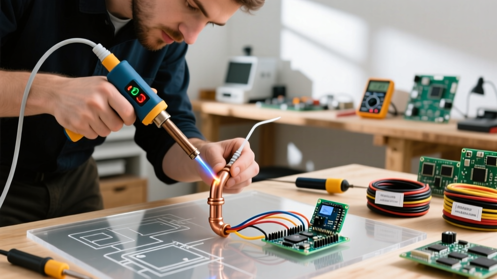

Navigating the Micro Soldering Bench: Beyond the Basics
Transitioning from standard through-hole or 0805 SMD work to true micro soldering requires a fundamental shift in both technique and equipment. When working with 0201 (0.6mm x 0.3mm) or 01005 (0.4mm x 0.2mm) components, BGA (Ball Grid Array) ICs, and ultra-fine flex cables, your margin for error drops to near zero. Investing in high-end micro soldering tools is only the first step; knowing how to calibrate, maintain, and troubleshoot them is what separates a successful board-level repair from a scrapped logic board.
This comprehensive FAQ and troubleshooting guide addresses the most common failure modes, setup errors, and operational edge cases encountered by technicians using modern micro soldering tools in 2026.
Core Micro Soldering Tools FAQ: Optics and Thermal Setup
What magnification and working distance do I actually need for 0201 components?
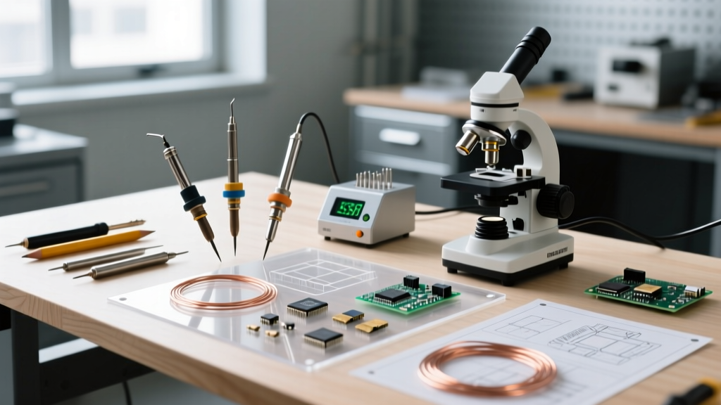
A common beginner mistake is purchasing a high-magnification stereo microscope without considering the working distance. Standard 7x-45x zoom stereo microscopes (like the widely used AmScope SM-4TP-BN, priced around $250) typically offer a working distance of roughly 40mm to 50mm. At this distance, there is insufficient physical clearance to maneuver a hot air rework nozzle, a micro-pencil, and a fume extractor simultaneously.
- The Fix: Add a 0.5x auxiliary Barlow lens to the objective. This reduces your maximum magnification slightly but doubles your working distance to approximately 90mm-100mm, providing the necessary clearance for tool manipulation.
- Lighting: Use a polarized ring light or dual-arm LED gooseneck lights positioned at 45-degree angles to eliminate glare from highly reflective flux residues and polished PCB solder masks.
Which micro-pencil handle and tip geometry is optimal for tight-pitch ICs?
For tight-pitch ICs (0.4mm or 0.5mm pitch), thermal recovery is vastly more important than peak wattage. The JBC CD-2BQE station paired with the T245-A handle (approx. $380 total) remains the industry benchmark due to its integrated heating element, which achieves 350°C in under two seconds. If you are using a Hakko FX-951, the T12-IL (0.15mm x 6mm blade) or T12-KF (knife tip) are essential for drag-soldering fine-pitch QFP chips.
Troubleshooting Matrix: Hot Air Rework Station Failures
Hot air rework stations, such as the Quick 861DW ($280) or JBC JTSE, are the workhorses of micro soldering. However, they are prone to specific pneumatic and thermal faults. Use the matrix below to diagnose bench issues.
| Symptom | Probable Cause | Exact Fix / Calibration |
|---|---|---|
| Airflow drops significantly; pump sounds strained. | Diaphragm pump degradation or clogged inline HEPA filter. | Replace the internal pump diaphragm kit (approx. $15). Check and replace the ceramic filter in the handpiece handle if it is darkened with carbonized flux. |
| Solder paste splatters violently under the nozzle. | Thermal shock causing flux solvents to boil instantly. | Implement a thermal ramp. Start at 120°C with 20L/min airflow for 30 seconds to evaporate solvents, then increase to 320°C-350°C for reflow. |
| Station displays 'E-01' or fails to heat upon lifting the wand. | Reed switch misalignment or broken flex wire in the handle. | Test the handle's continuity with a multimeter. If the internal ceramic heater pins are intact, realign the magnetic reed switch inside the wand holster. |
| Components 'tombstone' (stand up on one end) during reflow. | Uneven pad heating; one pad reaches reflow temperature before the other. | Use a PCB preheater (set to 100°C) to equalize board thermal mass. Alternatively, apply a small dot of tack flux to anchor the component before applying hot air. |
Consumables: Flux and Solder Paste Edge Cases
Expert Insight: The most misunderstood micro soldering tools are not electronic; they are chemical. Using the wrong flux viscosity for BGA reballing will result in bridged pads 100% of the time.
Why is my solder paste bridging under the BGA chip?
Bridging under a BGA (Ball Grid Array) usually stems from using a liquid or low-viscosity flux instead of a high-viscosity tack flux. For micro soldering tasks involving BGA reballing or stencil application, you must use a tack flux like Amtech NC-559-V2-TF or Chip Quik SMD291AX. These formulations are designed to hold the solder spheres in place and prevent them from migrating when the hot air fluidizes the solder.
How do I clean no-clean flux residues from under a micro-BGA?
Leaving activated flux under a BGA can lead to electrochemical migration (dendrite growth) over time, especially in humid environments. To clean without removing the IC:
- Apply a low-residue, high-purity flux cleaner (e.g., MG Chemicals 413A or Techspray Ecoline).
- Use a vacuum extractor tip placed at the opposite edge of the BGA from where you are injecting the cleaner.
- Gently heat the area to 80°C with a hot air gun to lower the surface tension of the cleaner, allowing capillary action to pull the solvent completely under the chip and out the other side.
Advanced FAQ: Grounding and ESD Protection
Micro soldering tools operate in environments where components are highly susceptible to Electrostatic Discharge (ESD). A single 30V spike can destroy the gate oxide of a modern MOSFET or logic chip, yet humans cannot feel a static shock until it reaches roughly 3,000V.
Is my ESD mat actually protecting my micro-components?
According to the ESD Association ANSI/ESD S20.20 standard, a working surface must have a point-to-point resistance between 1 x 10^6 and 1 x 10^9 ohms to safely dissipate static charges without causing a rapid discharge event that could damage sensitive silicon.
- Troubleshooting: If your mat reads > 10^10 ohms on a megohmmeter, it has likely accumulated a layer of insulating dust, oils from your skin, or silicone from aerosol sprays. Clean it with an ESD-safe mat cleaner (never use standard household glass cleaners, which contain insulating silicone compounds).
- Grounding the Iron: Verify that the tip of your JBC or Hakko station measures less than 2 ohms of resistance to your common point ground. If resistance is high, the internal grounding wire in the handpiece cord may be fractured.
How do NASA and IPC standards influence micro soldering tool selection?
When performing repairs on aerospace, medical, or high-reliability automotive boards, technicians must adhere to strict workmanship criteria. NASA's Electronic Parts and Packaging (NEPP) program and the IPC J-STD-001 standard dictate that solder joints must exhibit proper wetting, a smooth fillet, and no evidence of thermal damage to the PCB laminate. To meet these standards, your micro soldering tools must feature precise, closed-loop temperature control. Uncalibrated or open-loop irons that overshoot their target temperature by even 20°C can cause PCB delamination or pad lifting, instantly failing an IPC Class 3 inspection.
Summary: Maintaining Your Micro Soldering Investment
Mastering micro soldering tools requires treating your bench as an integrated ecosystem. Your microscope's working distance dictates your tool clearance; your hot air station's pneumatic health dictates your reflow profile; and your ESD grounding dictates the survival of the silicon you are manipulating. By systematically troubleshooting these elements—cleaning your optics, maintaining your pump diaphragms, and verifying your mat resistance—you ensure that your equipment performs flawlessly at the microscopic scale.