
Industrial Soldering: Beyond the Workbench
When engineers and procurement specialists evaluate the different types of soldering, the conversation must extend far beyond basic through-hole prototyping. In modern manufacturing, the choice of soldering methodology dictates production throughput, joint reliability under thermal cycling, and compliance with stringent sector-specific standards. Whether you are scaling a consumer electronics line or assembling high-voltage EV battery packs, selecting the correct thermal joining process is a critical engineering decision.
This guide breaks down the primary industrial soldering methods—wave, reflow, laser, and hard soldering (brazing)—detailing the exact alloys, equipment models, and failure modes associated with each. For foundational reliability metrics, industry professionals rely heavily on frameworks like the IPC J-STD-001 standard, which defines the requirements for soldered electrical and electronic assemblies across various performance classes.
Wave Soldering for High-Volume Mixed Technology
Wave soldering remains the backbone for high-volume printed circuit board (PCB) assembly featuring through-hole components or mixed-technology boards. The process involves passing the PCB over a pump-driven wave of molten solder alloy.
Equipment and Metallurgy
Modern industrial wave machines, such as the ERSA POWERFLOW N 65/75, utilize advanced nitrogen (N2) inerting systems. By reducing the oxygen concentration in the soldering environment to below 50 ppm, manufacturers can reduce dross generation (oxidized solder waste) by up to 40%. Given that lead-free SAC305 (96.5% Tin, 3.0% Silver, 0.5% Copper) solder costs roughly $25 to $35 per kilogram in bulk, dross reduction directly impacts the bottom line.
- Operating Temperature: The solder pot is typically maintained between 255°C and 265°C for SAC305, well above its 217°C liquidus point.
- Flux Application: Drop-jet or ultrasonic fluxers apply VOC-free, water-based fluxes (typically classified as ORL0 or ROL0 under IPC J-STD-004) at precise micro-liter volumes.
- Preheat Profile: Top and bottom IR heaters ramp the board to 110°C–130°C to prevent thermal shock and activate the flux.
Common Failure Modes
In wave soldering, solder bridging (shorts between adjacent pins) and icicles are prevalent. These are often caused by incorrect conveyor speeds (typically 3.5 to 5.0 feet per minute) or poor PCB pad design lacking adequate solder thieves. Furthermore, lifted pads can occur if the preheat gradient is too aggressive, causing rapid outgassing from the PCB laminate.
Reflow Soldering: The SMT Standard
Surface Mount Technology (SMT) relies almost exclusively on reflow soldering. Solder paste—a thixotropic mixture of microscopic alloy spheres and chemical flux—is stencil-printed onto pads, components are placed, and the entire assembly is passed through a multi-zone convection reflow oven.
Thermal Profiling and Equipment
High-end reflow ovens like the Heller 1809EXL feature 18 distinct heating zones, allowing for hyper-precise thermal profiling. Engineers use K-type thermocouples attached to critical components to map the board's thermal mass. For SAC305, the target Time Above Liquidus (TAL) is strictly maintained between 45 and 60 seconds, with a peak temperature of 235°C to 245°C.
Expert Insight: According to reliability data published by the NASA Electronic Parts and Packaging (NEPP) Program, excessive TAL in reflow soldering leads to excessive intermetallic compound (IMC) growth at the copper-tin interface. A thick, brittle Cu6Sn5 IMC layer significantly reduces the drop-shock survivability of Ball Grid Array (BGA) packages.
Defect Analysis in Microelectronics
As components shrink to 01005 (0.4mm x 0.2mm) imperial sizes, reflow dynamics become volatile. Tombstoning (drawbridging) occurs when one pad reaches reflow temperature before the other, creating an asymmetric wetting force that stands the component on end. Head-in-Pillow (HiP) defects in BGAs happen when the flux in the paste exhausts its activity before the solder sphere on the component melts, resulting in a false joint that passes initial electrical testing but fails under thermal expansion.
Laser and Induction Soldering: Selective Non-Contact Methods
For heat-sensitive components, flexible circuits, and automotive power electronics, traditional convection or iron-based methods are too blunt. Laser soldering provides localized, non-contact thermal energy.
Automotive and Medical Applications
Systems utilizing 915nm or 980nm diode lasers (such as those manufactured by Leister or FISON) deliver precise wattage (typically 30W to 150W) directly to the joint. A critical feature of modern laser systems is closed-loop pyrometer control. The pyrometer reads the infrared emission of the joint in real-time, adjusting laser power in milliseconds to maintain an exact temperature, preventing thermal damage to adjacent RF shielding or camera sensor modules.
In the medical device industry, laser soldering is preferred for joining micro-coils in pacemakers and neurostimulators, as it eliminates the risk of flux residue entrapment in hermetic seals. The typical joint cycle time is 1.5 to 3.0 seconds, making it highly efficient for automated robotic cells.
Hard Soldering (Brazing) in HVAC and Aerospace
While electronics engineers focus on soft soldering (below 450°C), the HVAC, plumbing, and aerospace sectors rely on hard soldering, universally termed brazing. This process joins base metals without melting them, using a filler metal that flows via capillary action.
AWS Standards and Joint Clearances
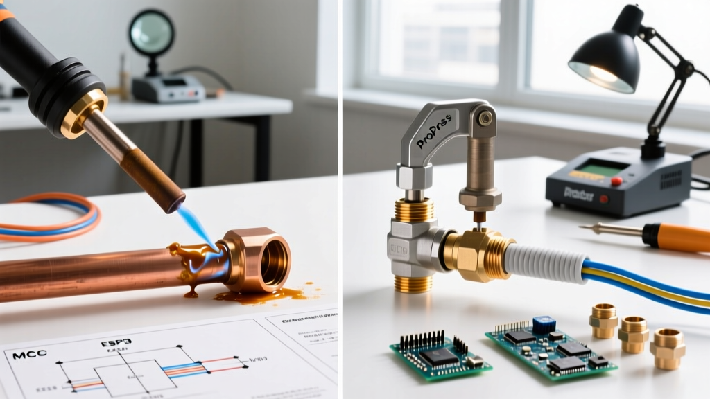
The American Welding Society (AWS) strictly governs brazing filler metals under the A5.8 specification. In commercial HVAC and refrigeration, copper-to-copper joints are typically brazed using Sil-Fos 5 (a copper-phosphorus alloy with 5% silver). The phosphorus acts as a built-in flux, eliminating the need for external chemical fluxes on pure copper.
- Temperature: Sil-Fos 5 flows at approximately 732°C (1350°F), requiring an oxy-acetylene torch.
- Joint Clearance: Capillary action requires a precise radial clearance of 0.002 to 0.005 inches at brazing temperature. If the gap is too wide, the filler metal will not be drawn into the joint; if too tight, flux entrapment or incomplete penetration occurs.
- Aerospace Variants: For joining stainless steel or Inconel in jet engines, nickel-based brazing pastes (like BNi-2) are used in vacuum furnaces at 1050°C, yielding joints with tensile strengths exceeding 60,000 psi.
Comparison Matrix: Industrial Soldering Methods
| Method | Typical Temp Range | Primary Industry | Standard Alloy / Filler | Relative Joint Cost |
|---|---|---|---|---|
| Wave Soldering | 255°C - 265°C | Consumer Electronics, Automotive ECU | SAC305, SnCuNi | $0.01 - $0.03 |
| Reflow (SMT) | 235°C - 245°C (Peak) | Telecom, Computing, Mobile Devices | SAC305, SAC405 (Paste) | $0.005 - $0.02 |
| Laser Soldering | 220°C - 280°C | Medical, Optics, EV Sensors | SnAg, AuSn (Preforms/Wire) | $0.15 - $0.50+ |
| Hard Soldering (Brazing) | 650°C - 1100°C | HVAC, Aerospace, Heavy Machinery | BCuP (Sil-Fos), BNi (Nickel) | $0.50 - $2.00+ |
Selecting the Right Flux Chemistry by Sector
The type of soldering dictates the flux chemistry, which is just as critical as the alloy. In consumer electronics, No-Clean (NC) fluxes are standard; their residues are benign and left on the board to save washing costs. However, in aerospace and high-reliability automotive applications, any residue poses a risk of electrochemical migration (dendrite growth) under high humidity and bias.
For these sectors, Water-Soluble (OA) fluxes are mandated, requiring rigorous post-solder cleaning using ultrasonic or batch aqueous washers. The cleanliness is then verified using an Omega meter or Ion Chromatography (IC) testing to ensure ionic contamination remains below 1.0 µg NaCl equivalent per square centimeter.
Summary: Aligning Process with Product Lifecycle
Understanding the different types of soldering is not merely an academic exercise; it is a core competency in Design for Manufacturing (DFM). Wave and reflow soldering offer unmatched economies of scale for PCB assembly, provided thermal profiles are strictly managed to prevent IMC overgrowth and tombstoning. Laser soldering solves the thermal constraints of miniaturized, heat-sensitive microelectronics, while hard soldering provides the mechanical and structural integrity required in heavy industrial and aerospace fluid systems. By matching the thermal delivery method, alloy metallurgy, and flux chemistry to the specific operational environment of the end product, engineers ensure long-term field reliability and regulatory compliance.