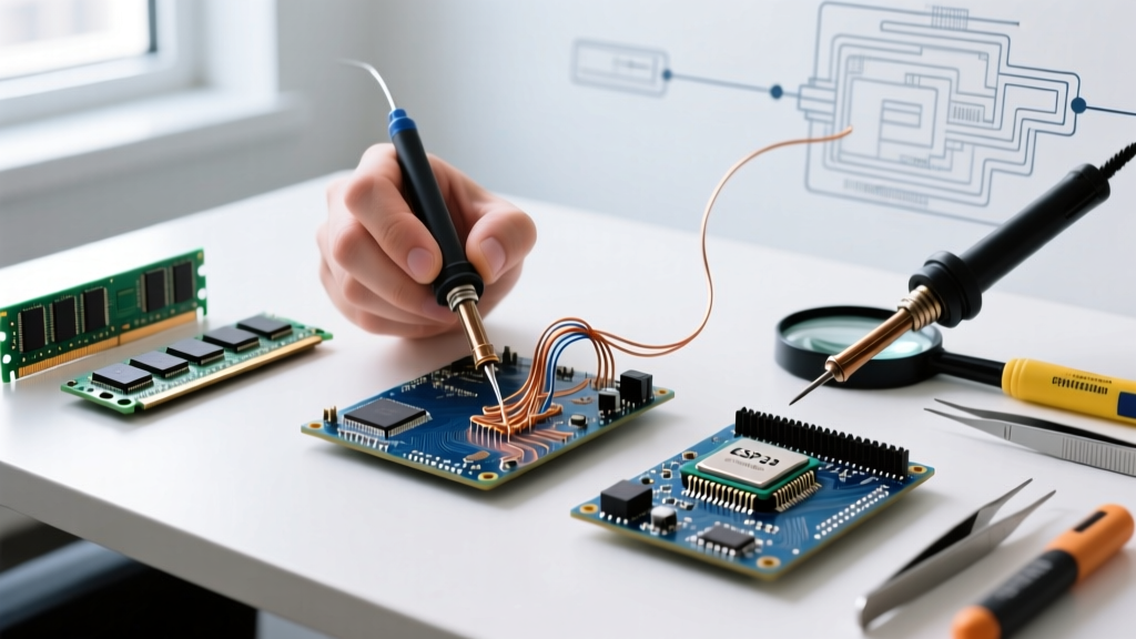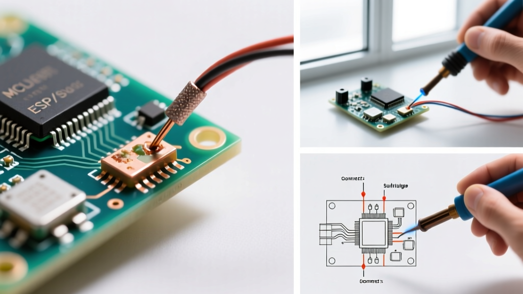

The Anatomy of a Perfect Joint vs. Bad Soldering
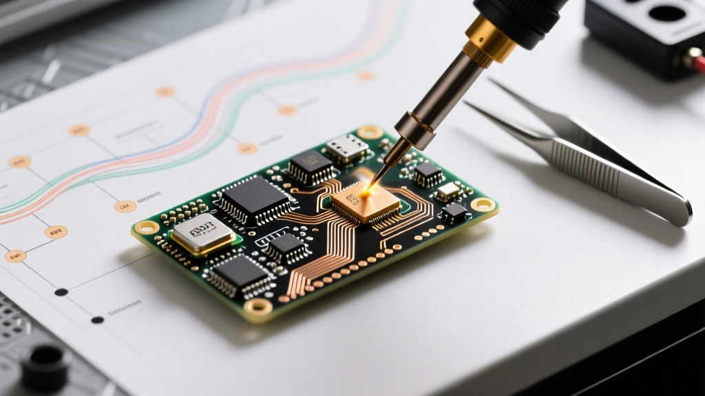
A reliable solder joint is not merely about sticking two metals together; it is a precise metallurgical bond. According to the IPC-A-610 standard for electronic assemblies, a perfect through-hole joint exhibits a smooth, concave fillet with a wetting angle of less than 90 degrees. The solder must flow seamlessly onto the copper pad and the component lead, forming a thin intermetallic compound (IMC) layer. When this process fails, you get bad soldering—a primary culprit behind intermittent shorts, high-resistance connections, and catastrophic field failures.
Expert Insight: Dullness in a leaded solder joint (Sn63/Pb37) usually indicates a disturbed joint or oxidation, whereas lead-free alloys (like SAC305) naturally dry with a slightly matte or grainy finish. Do not mistake the natural appearance of lead-free solder for a cold joint.
5 Common Types of Bad Soldering Joints
1. Cold Solder Joints
A cold joint occurs when the solder melts, but the copper pad or component lead does not reach the necessary temperature for proper wetting. The result is a bulbous, lumpy, and dull connection that resembles a cauliflower. Electrically, it introduces high resistance and mechanical fragility.
- Root Cause: Insufficient heat transfer, often due to using a soldering iron tip that is too small for the thermal mass of the joint, or failing to apply flux.
- The Fix: Apply a high-quality no-clean flux like Amtech NC-559-V2 ($35). Increase your iron temperature by 15°C to 20°C (up to 350°C for lead-free). Touch the iron to both the pad and the lead simultaneously for 2 to 3 seconds until the solder flows smoothly.
2. Solder Bridges (Shorts)
Common in fine-pitch SMD components (0603, 0805, or SOIC packages), a bridge happens when solder flows across two adjacent pads, creating a direct short circuit.
- Root Cause: Using too much solder, an oversized iron tip, or dragging the iron too slowly without adequate flux.
- The Fix: Do not panic. Apply liquid flux (e.g., MG Chemicals 8341) and use a high-quality desoldering braid like Chemtronics 80-1-2 (0.030-inch width). Place the wick over the bridge, press down with a flat chisel tip heated to 360°C, and drag slowly. Capillary action will pull the excess solder into the braid.
3. Disturbed Joints
If a component moves while the solder is transitioning from a liquid state back to a solid (crossing the solidus temperature line), the crystalline structure fractures. The joint will look grainy, cracked, or have visible frost lines.
- Root Cause: Bumping the board, tweezers slipping, or lack of mechanical support during cooling.
- The Fix: Simply reflow the joint. The addition of a tiny drop of fresh flux and reheating will allow the crystalline structure to reform properly.
4. Overheated Joints and Lifted Pads
Standard FR-4 PCBs have a glass transition temperature (Tg) around 130°C to 140°C. Dwelling a 400°C iron on a pad for more than 4 seconds can delaminate the epoxy, causing the copper trace to lift off the board entirely.
- Root Cause: Iron temperature set too high, dirty or oxidized tips failing to transfer heat (prompting the user to hold the iron longer), or lack of preheating for multi-layer boards.
- The Fix: Prevention is key. If a pad lifts, you must scrape the solder mask off the connected trace and run a 30 AWG bare copper wire to the next via. Use Kapton tape to secure the repaired trace.
5. Starved (Insufficient) Solder
The joint looks dry, and the outline of the component lead is sharply visible without a smooth fillet transitioning to the pad.
- Root Cause: Removing the solder wire too early, or poor wetting due to heavy oxidation on the component leads.
- The Fix: Clean the leads with isopropyl alcohol (99% IPA), apply flux, and feed a small amount of fresh 0.025-inch solder wire into the joint.
Troubleshooting Matrix: Defect Identification and Rework
| Defect Type | Visual Symptom | Primary Cause | Rework Action |
|---|---|---|---|
| Cold Joint | Dull, lumpy, bulbous, cauliflower shape | Low heat, lack of flux | Add flux, reflow at +20°C |
| Solder Bridge | Solder connecting adjacent pads | Excess solder, oversized tip | Desoldering wick + flux |
| Disturbed Joint | Grainy, frosted, visible micro-cracks | Movement during solidification | Reflow with fresh flux |
| Overheated | Burnt flux, lifted pads, scorched mask | Dwell time > 4s, temp > 380°C | Trace repair / jumper wire |
| Starved Joint | No concave fillet, sharp lead outline | Insufficient solder feed | Feed 0.025 inch solder + flux |
Essential 2026 Toolkit for Reworking Bad Soldering
To fix bad soldering, you need precise thermal control and high-quality consumables. Here is the professional-grade rework stack we recommend this year:
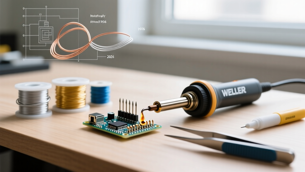
- Soldering Station: The Hakko FX-888D (~$115) remains the undisputed workhorse for through-hole rework. For SMD and field repairs, the Pinecil V2 ($26) utilizes a RISC-V processor and USB-C PD3.0 to reach 350°C in under 6 seconds.
- Flux: Amtech NC-559-V2 (~$40) for BGA and SMD rework, or Kester 186 Mildly Activated Rosin (~$12) for heavy-duty through-hole oxidation.
- Desoldering Braid: Chemtronics 80-Series ($10 to $15). Never use expired braid; oxidized copper will not wick solder.
- Cleaning: MG Chemicals 99.8% Isopropyl Alcohol and a stiff ESD-safe brush to remove corrosive flux residues post-rework.
Step-by-Step Rework Procedure
Follow this exact sequence to rescue a defective joint without damaging the PCB:
- Inspect and Clean: Examine the bad joint under a 10x loupe or microscope. Swab the area with 99% IPA to remove surface grime and old, burnt flux.
- Apply Fresh Flux: Dispense a generous amount of tacky flux over the joint. Flux is the chemical engine that removes oxidation and lowers the surface tension of the molten solder.
- Select the Right Tip: Use a bevel or chisel tip (e.g., Hakko T18-D24) to maximize surface area contact. Never use a conical (point) tip for rework; they have terrible thermal transfer.
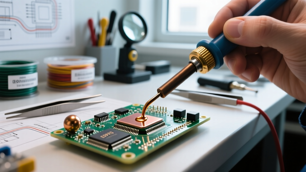
- Heat and Reflow: Apply the iron to the pad and lead simultaneously. For Sn63/Pb37, set the station to 320°C. For SAC305 lead-free, set it to 360°C. Hold for 2 to 3 seconds until the solder flashes into a liquid mirror.
- Remove and Cool: Pull the iron away and let the board air-cool. Do not blow on it; forced air can cause micro-fractures in the cooling alloy.
- Final Clean: Scrub the area with IPA and an ESD brush to prevent long-term dendritic growth from acidic flux residues.
Safety Warning: Lead-Free Rework
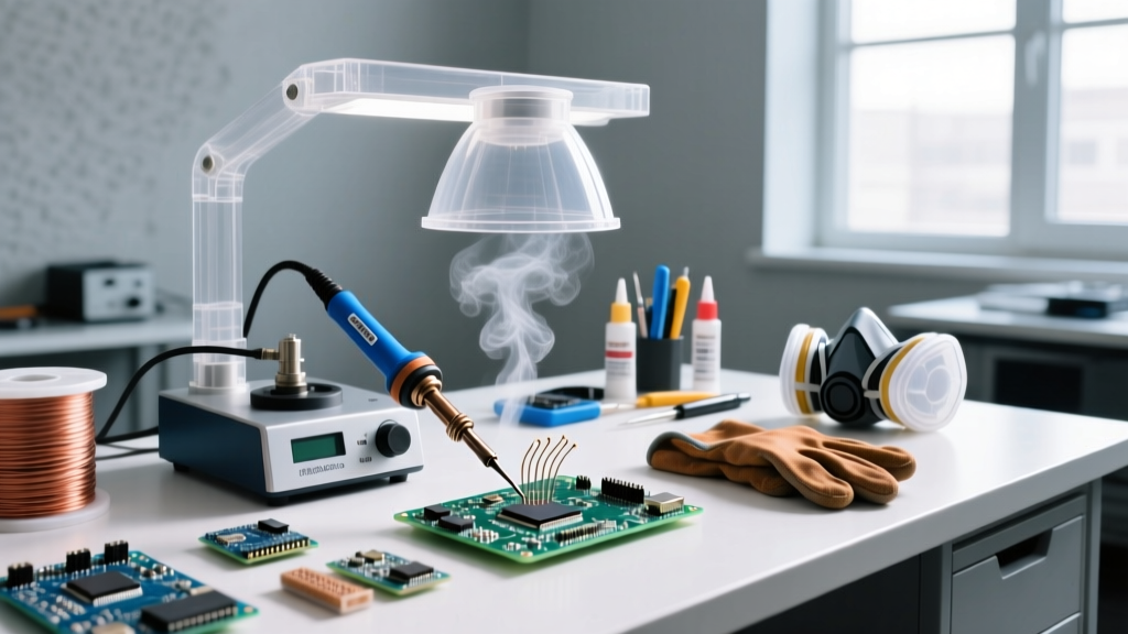
When reworking bad soldering on modern commercial electronics, you are likely dealing with lead-free SAC305 alloy. This requires higher temperatures (up to 380°C) and generates more aggressive fumes. Always use an active carbon fume extractor, such as the Hakko FA-400, positioned within 6 inches of the work area to prevent inhalation of colophony (rosin) fumes, a known respiratory sensitizer.
Prevention: Best Practices for Flawless Joints
The most cost-effective way to handle bad soldering is to prevent it. According to NASA Workmanship Standard 8739.3, proper preparation is mandatory for high-reliability joints.
- Always Tin Your Tip: Before turning off your station, melt a large blob of leaded solder over the iron tip. This sacrificial layer prevents the iron plating from oxidizing overnight.
- Use a Brass Sponge: Damp cellulose sponges cause rapid thermal shock to the iron's ceramic heating element, leading to premature failure and temporary temperature drops that cause cold joints. Use a dry brass wire sponge instead.
- Match Tip Mass to Joint Mass: If you are soldering a large ground plane via, a needle tip will instantly lose its heat, resulting in a cold joint. Switch to a heavy-duty chisel or screwdriver tip to maintain thermal equilibrium.
Mastering the rework of bad soldering joints separates beginners from seasoned electronics engineers. By understanding the metallurgy of wetting, utilizing the correct flux chemistry, and maintaining strict temperature discipline, you can salvage almost any botched PCB and ensure long-term electrical reliability.
For further foundational reading on through-hole and SMD techniques, consult the SparkFun Guide to Through-Hole Soldering.