
The Role of Perfboard in Modern Industrial Prototyping
While often dismissed as a hobbyist tool, soldering perfboard remains a critical bridge in professional engineering workflows. In 2026, as supply chain lead times for custom multi-layer PCBs continue to fluctuate between 14 and 28 days for low-volume runs, industrial R&D teams rely heavily on high-grade perfboards to build custom test jigs, aerospace sensor nodes, and low-volume medical diagnostic rigs. When executed correctly, a perfboard assembly can meet rigorous environmental and electrical standards, providing a reliable platform for validation before committing to expensive fab runs.
The transition from a breadboard to a soldered perfboard prototype introduces permanent mechanical and electrical bonds. However, industrial applications demand more than simple point-to-point wiring; they require strict thermal management, substrate material selection, and adherence to workmanship standards like IPC-A-610 Class 2 or Class 3.
Material Science: Selecting the Right Substrate
The foundation of any reliable prototype is the substrate. Standard phenolic (paper-based) boards are inadequate for industrial environments due to low thermal thresholds and moisture absorption. Professional engineers must specify high-performance laminates.
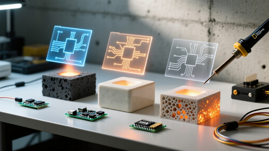
Comparative Matrix: Industrial Perfboard Substrates
| Material | Designation | Glass Transition (Tg) | Dielectric Strength | Avg. Cost (4x6 in.) | Primary Industrial Use Case |
|---|---|---|---|---|---|
| Phenolic | FR-2 / XPC | 105°C | Low | $2.50 - $4.00 | Consumer electronics mockups (non-critical) |
| Woven Glass Epoxy | FR-4 (G10/G11) | 135°C - 170°C | High | $6.50 - $9.00 | Automotive test rigs, industrial IoT nodes |
| Polyimide | Kapton / Flex | > 280°C | Very High | $18.00 - $24.00 | Aerospace, high-vibration wearable sensors |
For 90% of industrial test equipment, FR-4 (specifically G10/G11 grade) is the mandatory baseline. Vector Electronics' 8801 series, for example, features plated-through holes (PTH) with a 0.042-inch diameter and a 10-microinch gold flash over nickel barrier. This PTH construction is vital; it prevents pad lifting during rework and allows for reliable via-stitching when routing ground planes.
Plating and Pad Chemistry: ENIG vs. HASL
When sourcing FR-4 perfboard for mixed-signal or high-frequency prototypes, the copper pad plating dictates solderability and shelf life. In 2026, Electroless Nickel Immersion Gold (ENIG) has largely superseded Hot Air Solder Leveling (HASL) for professional prototyping boards.
- ENIG (Gold Flash): Provides an ultra-flat surface, ideal if you are adapting surface-mount (SMD) breakout boards onto the perfboard grid. The gold protects the underlying nickel from oxidation, offering a 12+ month shelf life in standard ESD storage.
- HASL (Lead-Free): Cheaper and offers a thicker solder base, but the uneven topography can complicate the installation of tight-pitch DIP sockets or precision resistor networks.
Thermal Management and Soldering Execution
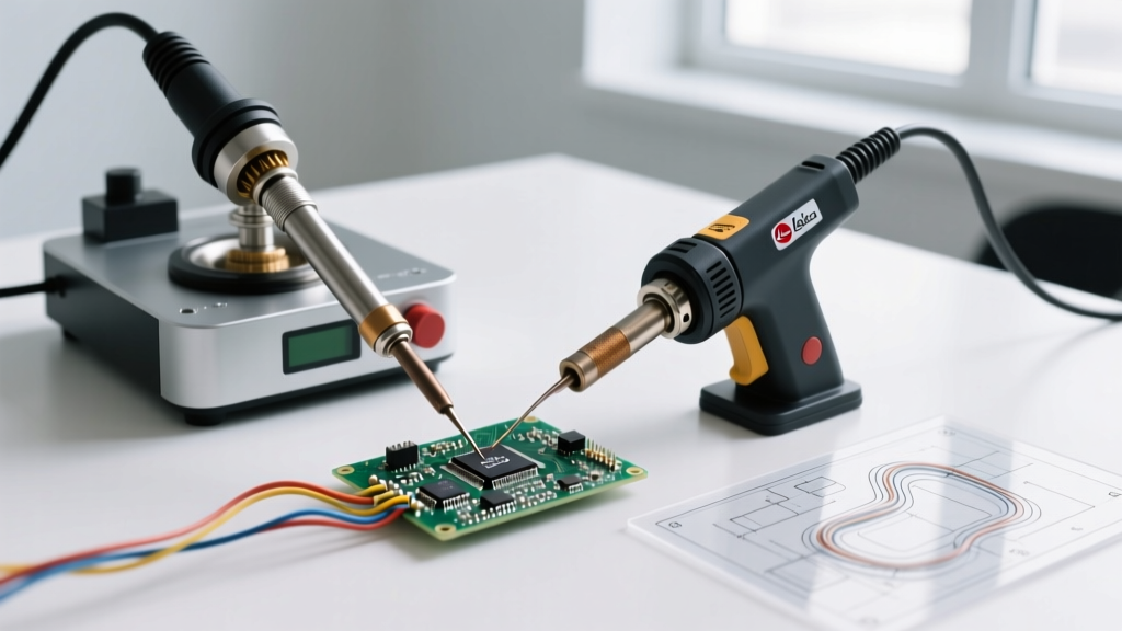
Soldering perfboard in an industrial context requires strict adherence to thermal profiles. The days of using a generic 40W iron with a chisel tip are over. Modern assemblies utilize lead-free alloys like SAC305 (Sn96.5/Ag3.0/Cu0.5), which has a liquidus temperature of 217°C. To achieve proper wetting without damaging the FR-4 epoxy or the plated-through holes, the iron tip must be precisely managed.
Thermal Mass Warning: When soldering large ground wires to a perfboard's continuous copper ground plane, the plane acts as a massive heat sink. Applying a standard 350°C iron directly will result in a cold joint or pad delamination. Always pre-heat the board to 110°C using a bottom-side preheater (like the Hakko FR-830) or use a high-wattage cartridge system (e.g., JBC C245-945) that can dump 130W of instantaneous thermal recovery into the joint.
Optimized Tooling and Consumables
To meet IPC-A-610 Class 2 and Class 3 requirements for electronic assemblies, engineers must utilize specific tooling:
- Soldering Station: JBC CD-2BQE or Weller WT1012. These stations offer sub-second thermal recovery, crucial for maintaining a consistent 360°C tip temperature when transitioning between small signal pads and heavy power vias.
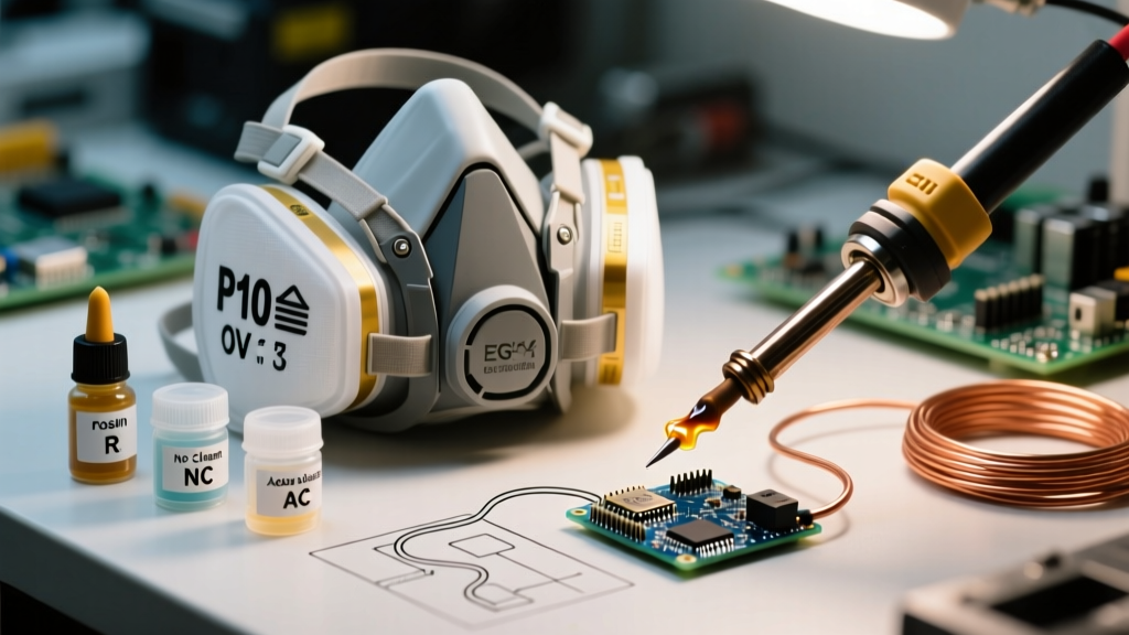
- Flux: Do not rely solely on the rosin core inside the solder wire. Apply an additional no-clean, tacky flux such as Amtech NC-559-V2-TF or Chip Quik SMD291AX. This reduces surface tension, prevents bridging on tight 0.1-inch grids, and minimizes the dwell time required to form a proper fillet.
- Dwell Time Limit: Maximum 3 seconds per joint. Exceeding this threshold degrades the epoxy-to-copper bond strength, leading to micro-fractures that fail under thermal cycling.
Wire Routing, Strain Relief, and Mechanical Integrity
Industrial environments subject prototypes to vibration, thermal expansion, and physical handling. Point-to-point wiring on a perfboard must be mechanically secured, not just electrically connected.
Wire Selection and Routing
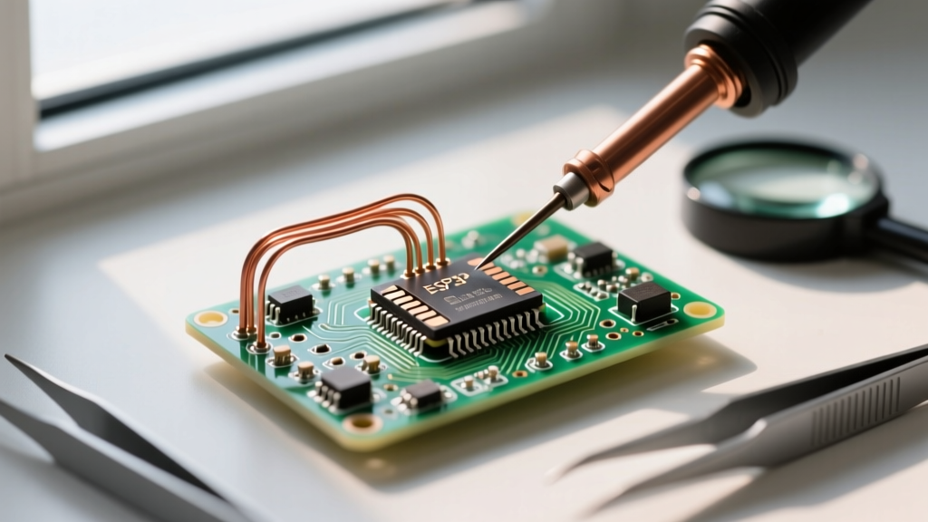
Avoid standard PVC-jacketed hookup wire for high-reliability nodes. Instead, specify PTFE (Tefzel) insulated wire (e.g., Mil-Spec MIL-W-16878/4). PTFE withstands soldering temperatures up to 450°C without melting back, allowing for extremely clean, flush stripping and soldering close to the board surface. For signal lines, AWG 28 to AWG 30 is standard; for power rails exceeding 2A, use AWG 22 or AWG 20 stranded copper.
Mechanical Anchoring
Components with significant mass (e.g., TO-220 voltage regulators, large electrolytic capacitors, or heavy DB9 connectors) must never rely solely on their soldered leads for mechanical support. The industry standard practice is to apply a high-modulus RTV silicone, such as Dow Corning 3140 or Loctite 5035, underneath the component body. This provides critical strain relief and dampens high-frequency vibrations that would otherwise fatigue and crack the solder fillets over time.
Compliance and Workmanship Standards
When a perfboard prototype is destined for an aerospace test rig or a medical validation setup, the assembly must be documented and inspected against recognized standards. The NASA Electronic Parts and Packaging (NEPP) Program provides exhaustive workmanship manuals (such as NASA-STD-8739.3) that dictate exact fillet shapes, wetting angles, and insulation clearances for through-hole and wire-to-board connections.
Key inspection criteria for industrial perfboard assemblies include:
- Fillet Geometry: A smooth, concave fillet with a contact angle of less than 90 degrees. Convex or bulbous joints indicate insufficient flux or inadequate heating.
- Wicking: Solder should be visible wicking up the component lead and into the plated-through hole barrel. For Class 3, 75% minimum barrel fill is often required, though 50% is acceptable for standard Class 2 prototyping.
- Cleanliness: Even when using 'no-clean' fluxes, industrial protocols often mandate a post-solder wash using an automated ultrasonic cleaner with a saponifier, followed by a deionized water rinse and baked drying, to prevent electrochemical migration (dendrite growth) in high-humidity test chambers.
Transitioning from Perfboard to Production
Perfboard is a validation tool, not a mass-production solution. As a general rule of thumb in 2026 hardware development, once a design requires more than 50 units, or if the circuit operates above 50 MHz (where parasitic capacitance and inductance of 0.1-inch grid wiring degrade signal integrity), it is time to migrate to a custom PCB. However, for bespoke testing fixtures, one-off calibration rigs, and low-volume sensor arrays, mastering the art of soldering perfboard remains an indispensable, cost-saving skill in the professional engineer's arsenal.
For those new to advanced through-hole techniques, reviewing foundational guides like the SparkFun Through-Hole Soldering Tutorial can help bridge the gap between basic hobbyist practices and the rigorous demands of industrial prototyping.