
The Shift from Connectors to Soldered Joints in Commercial Lighting
In the architectural and commercial lighting sectors, the reliability of linear illumination is paramount. As of 2026, high-density COB (Chip-on-Board) and advanced 2835 SMD LED tapes are pushing power densities up to 15W per foot. While DIY enthusiasts often rely on solderless quick-connectors, these mechanical joints are increasingly rejected in commercial specifications. Vibration, thermal cycling, and long-term oxidation cause connector pins to lose tension, leading to voltage drops, flickering, and catastrophic arcing in high-amperage runs.
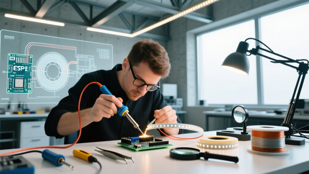
Mastering the art of soldering LED tape for industry applications requires moving beyond basic hobbyist techniques. It demands an understanding of flexible printed circuit board (FPCB) thermodynamics, RoHS-compliant metallurgy, and strict adherence to commercial quality standards. This guide details the professional methodology for soldering LED tape in high-volume manufacturing and premium architectural installations.
Material Selection: Alloys, Flux, and FPCB Substrates
Commercial LED tape is typically manufactured on a 2oz copper FPCB with a polyimide or high-grade FR-4 backing. The copper pads are small (often 2mm x 2mm) and highly susceptible to thermal delamination if abused. Selecting the correct consumables is the first critical step.
Solder Alloy: SAC305 vs. Leaded Alternatives
For commercial and architectural projects, lead-free solder is mandatory to comply with global RoHS (Restriction of Hazardous Substances) directives. The industry standard is SAC305 (96.5% Tin, 3.0% Silver, 0.5% Copper). SAC305 has a higher melting point (217°C - 220°C) compared to traditional Sn63/Pb37 (183°C). This higher thermal threshold actually benefits LED tape, as the resulting joint is more resistant to the ambient heat generated by high-output LED diodes during continuous operation.
Flux Selection for Micro-Pads
Never use acid-core plumbing flux on electronics. For LED tape, professionals use a No-Clean Rosin-based flux (such as Kester 245 or MG Chemicals 8341). No-clean fluxes leave a benign, non-conductive residue that will not cause short circuits between the tightly spaced positive and negative pads on 12V or 24V tape. Furthermore, applying a small dab of tack flux to the FPCB pad prior to soldering breaks up surface oxidation and ensures rapid wetting, drastically reducing the time the iron needs to dwell on the pad.
Wire Gauge and Voltage Drop Matrix for 24V Systems
When soldering LED tape, the wire gauge must be matched to the amperage draw to prevent voltage drop and subsequent overheating of the solder joint. Commercial installs heavily favor 24V constant-voltage systems over 12V to halve the current draw for the same wattage. Below is the 2026 industry matrix for 24V architectural tape.
| Tape Wattage (W/ft) | Current per 16ft Reel (A) | Recommended Feed Wire (AWG) | Max Run Length (Single Feed) |
|---|---|---|---|
| 1.5W - 3.0W | 1.0A - 2.0A | 20 AWG Stranded Silicone | 16 ft (5m) |
| 4.0W - 6.0W | 2.6A - 4.0A | 18 AWG Stranded Silicone | 10 ft (3m) |
| 8.0W - 12.0W | 5.3A - 8.0A | 16 AWG Stranded Silicone | 6 ft (1.8m) |
| 14.0W+ (COB) | 9.3A+ | 14 AWG Stranded Silicone | 4 ft (1.2m) w/ Dual Feed |
Note: Always use stranded silicone-insulated wire. Silicone withstands high soldering temperatures without melting back up the jacket, and its flexibility prevents mechanical stress on the rigid solder joint during installation.
Step-by-Step Commercial Soldering Protocol
Achieving a reliable joint on an FPCB requires a strict, repeatable process. The primary enemy is 'pad lift,' where excessive heat dissolves the adhesive bonding the copper trace to the substrate, causing the pad to peel away entirely.
- Prep the Wire: Strip exactly 4mm of insulation. Twist the strands tightly to prevent fraying.
- Pre-Tin the Wire: Apply a minimal amount of SAC305 solder to the stripped wire. The wire should look silver and glossy, not a dull, bulbous blob.
- Prep the FPCB Pad: If the LED tape has a silicone IP65 coating, carefully score and peel back exactly 3mm of the coating using a scalpel. Do not use chemical solvents, which can degrade the FPCB adhesive.
- Apply Flux: Dip a precision swab in no-clean flux and apply a micro-drop to the copper pad.
- Pre-Tin the Pad: Touch the iron tip to the pad for exactly 1 to 1.5 seconds to deposit a microscopic layer of solder. Remove the iron.
- The Final Joint: Hold the pre-tinned wire flat against the pre-tinned pad. Apply the iron to the top of the wire (not the pad). The existing solder on both surfaces will instantly reflow and merge. Total dwell time must not exceed 2.5 seconds.
- Cooling: Hold the wire perfectly still for 3 seconds while the SAC305 alloy solidifies. Moving the wire during the 'plastic' phase of cooling will result in a fractured, high-resistance cold joint.
Tooling Requirements for High-Volume Production
You cannot achieve commercial results with a $20 hardware store iron. Temperature stability and thermal recovery are critical when soldering dozens of joints in succession.
- Station: The Hakko FX-951 or Weller WE1010 are industry workhorses. Both offer rapid thermal recovery, ensuring the tip temperature doesn't plummet when touching the copper plane of the LED tape.
- Tip Geometry: Avoid standard chisel tips, which are too wide for 2mm pads. Use a micro-pencil (Hakko T12-IL) or a bevel tip (Weller RT4). The bevel tip provides a flat surface for heat transfer while keeping the overall footprint small enough to avoid shorting adjacent pads.
- Temperature Setting: Set the station to 350°C (662°F). While this seems high compared to the 220°C melting point of SAC305, the delta is necessary to compensate for the instantaneous heat sink effect of the copper trace.
Quality Control: Meeting IPC-A-610 Class 2 Standards
Commercial lighting assemblies are generally evaluated under IPC-A-610 Class 2 (Dedicated Service Electronic Products), which demands extended life and high performance. According to the IPC Standards registry, a compliant solder joint on an LED tape must exhibit a smooth, continuous fillet that wets the entire pad and the wire circumference. The solder should have a shiny, concave appearance. Bulbous, convex, or dull grey joints are immediate grounds for rejection in professional QA environments.
Industry Insight: The U.S. Department of Energy's Solid-State Lighting portal notes that thermal management is the leading factor in LED lumen depreciation. A poorly soldered, high-resistance joint acts as a localized heater, accelerating the degradation of the adjacent SMD phosphor layer and causing visible color-shifting in architectural coves.
Troubleshooting Edge Cases in the Field
Even with perfect technique, environmental variables can disrupt the soldering process. Here is how to handle common commercial edge cases:
Edge Case 1: Solder Wicking Under the IP65 Coating
The Problem: When soldering waterproof LED tape, capillary action pulls molten solder under the silicone extrusion, creating a rigid, brittle point that snaps when bent.
The Solution: Use a thermal wire stripper to remove the silicone coating cleanly without scoring the copper trace. Apply a tiny dot of high-temp RTV silicone over the finished joint to restore the IP rating and provide strain relief, rather than relying on the tape's original coating.
Edge Case 2: Cold Joints on High-Density COB Tape
The Problem: COB tapes feature a massive, continuous copper plane to dissipate heat from the dense diode array. This plane acts as a giant heatsink, pulling heat away from the iron tip and causing the solder to freeze before it wets the pad.
The Solution: Switch to a slightly larger chisel tip (e.g., Hakko T12-D24) to maximize surface contact area. Increase the station temperature to 380°C (716°F) temporarily, and apply flux generously to lower the surface tension and accelerate wetting.
Conclusion
Soldering LED tape for commercial and architectural applications is an exercise in precision thermodynamics. By abandoning mechanical connectors in favor of properly executed SAC305 solder joints, utilizing the correct wire gauges, and adhering to IPC-A-610 quality standards, integrators can guarantee lighting installations that remain flawless for tens of thousands of hours. In the high-stakes world of architectural lighting, the soldering iron remains the ultimate tool for reliability.