
Whether you are assembling heavy-gauge automotive wiring or repairing vintage audio equipment, a high-wattage soldering gun is an indispensable tool in the electrical DIY arsenal. Unlike standard pencil irons, soldering guns deliver massive thermal mass and rapid heat-up times, making them ideal for large terminals and thick copper traces. However, their high-current, transformer-based designs (or high-wattage ceramic heaters in modern variants) introduce unique failure modes. In this comprehensive 2026 troubleshooting guide, we break down the most common hardware faults, thermal equilibrium issues, and maintenance protocols to keep your workstation running flawlessly.
Critical Troubleshooting Matrix: Symptoms and Solutions
Before opening up the chassis of your tool, use this diagnostic matrix to isolate the root cause of your hardware or metallurgical failures. This table covers both classic transformer models (like the Weller D550) and modern high-wattage ceramic stations (like the Hakko FX-601).
| Symptom | Probable Root Cause | Diagnostic Step | Corrective Action |
|---|---|---|---|
| Tool fails to heat entirely | Trigger switch arcing or primary coil failure | Test continuity across the trigger switch with a multimeter. | Replace the micro-switch or clean contacts with electrical contact cleaner. |
| Intermittent heating / flickering bulb | Loose secondary loop connection at the tip base | Visually inspect the copper loop screws for carbon buildup. | Remove screws, sand the contact pads with 400-grit paper, and retorque. |
| Solder beads up and refuses to wet | Severe tip oxidation or flux exhaustion | Check if the tip appears black and crusty when heated. | Apply Kester Tip Tinner compound; never use abrasive files on plated tips. |
| Takes over 15 seconds to melt 63/37 solder | Thermal mass mismatch (massive ground plane) | Assess the pad size and copper pour of the target joint. | Switch to a larger chisel tip or preheat the PCB to 100°C. |
| Sparking inside the tool housing | Degraded wiring insulation near the transformer | Unplug immediately and open the chassis in a well-lit area. | Apply heat-shrink tubing or replace the primary AC wiring harness. |
Step-by-Step Diagnostics for Heating Failures
When your tool refuses to reach the 700°F (370°C) threshold required for standard 63/37 Sn/Pb eutectic solder, the issue usually lies in the power delivery circuit. Here is how to troubleshoot the two most common architectures on the market today.
1. Transformer-Based Guns (e.g., Weller D550 / D650)
These tools use a step-down transformer to convert 120V AC mains into a low-voltage, high-amperage current (often exceeding 200 amps) that passes directly through the copper tip loop. If the gun is dead:
- Test the Trigger Switch: Unplug the tool. Set your multimeter to continuity mode. Probe the two terminals on the trigger switch. Pull the trigger. If there is no beep, the internal copper contacts have pitted from repeated inductive arcing. Replace the switch assembly (typically a $6 to $12 part).
- Check the Primary Coil: If the switch is functional, probe the two main prongs on the AC plug while holding the trigger down. You should read a low resistance (usually between 2 and 5 ohms). An infinite reading (OL) indicates a blown thermal fuse inside the transformer winding or a severed primary coil. The unit must be replaced or professionally rewound.
- Inspect the Secondary Loop: The copper tip is held by two slotted screws. Over time, thermal cycling causes oxidation between the tip and the secondary bus bars. Remove the tip, clean the mating surfaces with isopropyl alcohol and a brass wire brush, and tighten the screws firmly to minimize contact resistance.
2. Ceramic Heater Pistols (e.g., Hakko FX-601)
Modern high-wattage pistols use a 60W to 100W ceramic heating element paired with a thermistor for closed-loop temperature control. If an FX-601 fails to heat:
- Measure the Heater Resistance: Access the 4-pin connector inside the handle. The heating element pins should show approximately 14 to 16 ohms at room temperature. An open circuit means the ceramic heater (Part #A1150) has cracked and requires a $15 replacement.
- Verify the Sensor: The thermistor pins should read around 1 to 2 ohms. If the station displays an error code (like 'H-E' or 'S-E'), the sensor wire is broken, often due to excessive flexing of the silicone cord.
Metallurgical Troubleshooting: Wetting and Cold Joints
Even with a perfectly functioning tool, poor metallurgical practices will result in failed joints. According to the IPC J-STD-001 standard for soldered electrical assemblies, a compliant joint must exhibit a smooth, continuous fillet with a concave shape and a shiny finish (for leaded alloys).
Expert Insight: A 'cold joint' is rarely caused by the solder cooling too quickly in ambient air. It is almost always the result of insufficient thermal transfer during the liquidus phase. If the base metal does not reach the melting point of the alloy, the flux cannot clear the oxides, resulting in a grainy, disturbed, or non-wetting joint.
The Fix: Always apply the soldering gun tip to the pad and the component lead simultaneously. Wait 1.5 to 2 seconds for the thermal mass to equalize, then feed the solder wire directly into the joint—not onto the tip of the gun. For heavy-gauge wires (10 AWG or larger), strip the wire, twist the strands, apply a liberal amount of Rosin Mildly Activated (RMA) paste flux, and pre-tin the wire before attempting to solder it to a terminal lug.
Tip Degradation and Oxidation Recovery
Soldering gun tips are constructed from a highly conductive copper core plated with a thin layer of iron to prevent the molten solder from dissolving the copper. When this iron layer is exposed to high temperatures without a protective layer of solder, it rapidly oxidizes, turning black and refusing to transfer heat.
Recovery Protocol:
- Heat the gun to a moderate temperature (approx. 500°F / 260°C).
- Dip the oxidized tip into a pot of Tip Tinner (a mixture of phosphoric acid, rosin flux, and fine solder powder).
- Agitate gently for 3 to 5 seconds. The acid will strip the oxidation, and the solder powder will immediately wet the exposed iron.
- Wipe the tip on a damp cellulose sponge or brass wool, and immediately apply a thick coat of fresh 63/37 solder to protect it from re-oxidizing.
Warning: Never use sandpaper, files, or a Dremel tool to clean a modern soldering tip. Doing so will strip the iron plating entirely, destroying the tip in a matter of minutes as the molten solder eats through the raw copper core.
Frequently Asked Questions (FAQ)
Why do search engines autocorrect my query to 'soldering gin'?
If you have ever typed quickly and seen search engines suggest 'soldering gin' instead of your intended tool, you are not alone. This is a widespread typographical error caused by the proximity of the 'U' and 'I' keys on standard QWERTY keyboards. There is no such chemical or tool as 'soldering gin' in the electronics industry; it is strictly a misspelling of 'soldering gun.' Always ensure you are searching for the correct terminology to find accurate technical manuals and safety data sheets.
Is it safe to use a soldering gun on delicate PCBs?
Generally, no. Classic transformer soldering guns generate a massive alternating magnetic field at the tip due to the high-amperage AC current passing through the loop. This electromagnetic interference (EMI) can induce voltage spikes in sensitive CMOS components, potentially frying microcontrollers or MOSFETs. Furthermore, the sheer thermal mass and rapid heat transfer can easily lift copper pads from standard FR-4 fiberglass circuit boards. For delicate PCB work, use a temperature-controlled pencil iron (like a Weller WE1010 or Hakko FX-888D) set to 650°F (343°C).
How often should I replace the copper tip loop on a Weller gun?
Under normal DIY usage (a few hours a week), a standard copper tip loop will last 1 to 2 years. However, if you are soldering heavily oxidized surfaces, using aggressive water-soluble (OA) fluxes, or constantly leaving the gun powered on between joints, the tip will pit and erode much faster due to chemical corrosion and thermal stress. Keep a 3-pack of replacement tips (such as the Weller CT6F7) in your toolkit; they cost roughly $15 and take less than 60 seconds to swap out.
What safety precautions are required for soldering fumes?
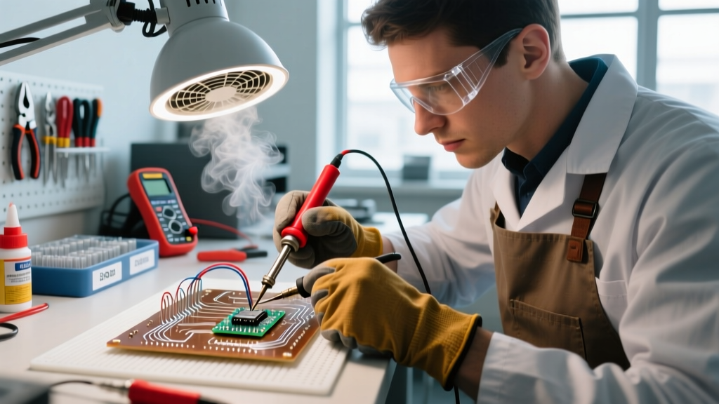
The primary health hazard in soldering is not the lead (which does not vaporize at soldering temperatures), but the colophony (rosin) flux fumes. When heated, rosin decomposes into aliphatic aldehydes and hydrochloric acid, which are known respiratory sensitizers and can trigger occupational asthma. The CDC and NIOSH strongly recommend the use of local exhaust ventilation (LEV). Always use a fume extractor equipped with a HEPA and activated carbon filter positioned within 6 inches of the soldering joint, or work in a room with high-volume cross-ventilation.
Final Maintenance Checklist
To ensure your equipment survives the demands of a busy 2026 workshop, adopt this end-of-session maintenance routine:
- Tin Before Power-Down: Always melt a large blob of flux-cored solder onto the tip right before turning off the tool. This sacrificial layer will oxidize instead of the tip's iron plating as it cools.
- Inspect the Power Cord: Soldering guns are frequently dragged across workbenches. Check the AC strain relief for micro-tears or exposed copper strands.
- Clean the Housing: Wipe down the thermoplastic handle with a mild degreaser to remove flux residue and skin oils, which can degrade the plastic over time and make the trigger slippery.
By understanding the electrical architecture of your tool and respecting the metallurgy of your solder alloys, you can eliminate 99% of common workstation frustrations. For further reading on professional assembly techniques, consult the Weller Tools official support library for model-specific exploded views and wiring diagrams.