
The Hidden Thermal Dangers of Soldering LED Components
Soldering LED assemblies is often mistakenly grouped with general-purpose electronics work. However, light-emitting diodes—whether they are flexible WS2812B strips, high-density COB arrays, or discrete 0805 SMD packages—are exceptionally vulnerable to thermal shock and prolonged heat exposure. The epoxy lenses used to encapsulate standard LEDs can yellow, crack, or delaminate when subjected to temperatures exceeding 260°C (500°F) for more than a few seconds. Furthermore, the copper pads on flexible printed circuits (FPCs) are notoriously prone to lifting if the iron dwells too long.
In this comprehensive guide, we break down the exact methodologies, thermal profiles, and material choices required for soldering LED projects flawlessly in 2026. Whether you are building custom architectural lighting or repairing microscopic SMD indicators, mastering these techniques will save you from dead pixels and ruined PCBs.
Essential Gear for Precision LED Work
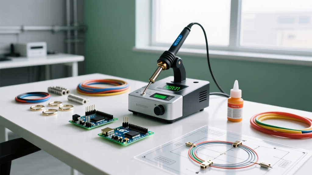
To achieve reliable joints without destroying heat-sensitive semiconductor junctions, you must abandon cheap, unregulated irons. Precision temperature control and rapid thermal recovery are non-negotiable.
- Soldering Station: The Hakko FX-888D (approx. $115) remains an industry standard for bench work due to its stable T18 tip ecosystem. For portable or tight-budget setups, the Pinecil V2 ($26) offers incredible thermal recovery via its RISC-V processor and supports interchangeable TS100 tips.
- Tip Selection: Use a chisel tip (e.g., Hakko T18-D12 or Pinecil D12) for LED strips to maximize surface area contact. For discrete SMD LEDs, switch to a micro-pencil or knife tip (e.g., T18-I) to isolate heat to a single 1mm pad.
- Solder Alloy: Leaded 63/37 (Tin/Lead) rosin-core solder is vastly superior for manual LED work due to its lower melting point (183°C) and eutectic properties, which prevent the joint from remaining in a fragile semi-solid state. Kester 245 0.031-inch ($12/spool) is the gold standard. Avoid thick 0.062-inch solder, which requires excessive heat to melt.
- Flux: Do not rely solely on the rosin core inside your solder wire. A high-quality tacky flux like Chip Quik NC191 or Amtech NC-559 ($15/syringe) drastically reduces the required dwell time by improving wetting.
- Wire Choice: For LED strips, use 20 AWG to 22 AWG stranded silicone wire. Silicone insulation will not melt or shrink back when the iron touches it, unlike PVC wire, which releases toxic fumes and exposes bare copper.
Thermal Profiles: Temperature and Dwell Time Matrix
According to the IPC J-STD-001 standards for soldered electrical assemblies, thermal management is critical for component longevity. Below is the recommended thermal matrix for various LED formats. Note that 'Dwell Time' refers to the maximum continuous contact time the iron should touch the pad.
| LED Format | Recommended Iron Temp | Max Dwell Time | Preferred Tip Style | Failure Risk if Exceeded |
|---|---|---|---|---|
| WS2812B / SK6812 Strips | 300°C - 320°C | 2.0 - 3.0 seconds | Chisel (1.2mm - 2.0mm) | Pad delamination, dead data-out pin |
| COB Flexible Strips | 280°C - 300°C | 1.5 - 2.0 seconds | Chisel or Bevel | Phosphor layer burn, localized dark spots |
| High-Power SMD (Cree/Luxeon) | 320°C - 350°C | 3.0 - 5.0 seconds | Wide Chisel / Spatula | Thermal pad separation, lens yellowing |
| Discrete 0805 / 1206 SMD | 300°C - 320°C | 1.0 - 2.0 seconds | Micro-pencil / Knife | Component cracking, solder wicking |
Step-by-Step: Soldering WS2812B and Addressable Strips
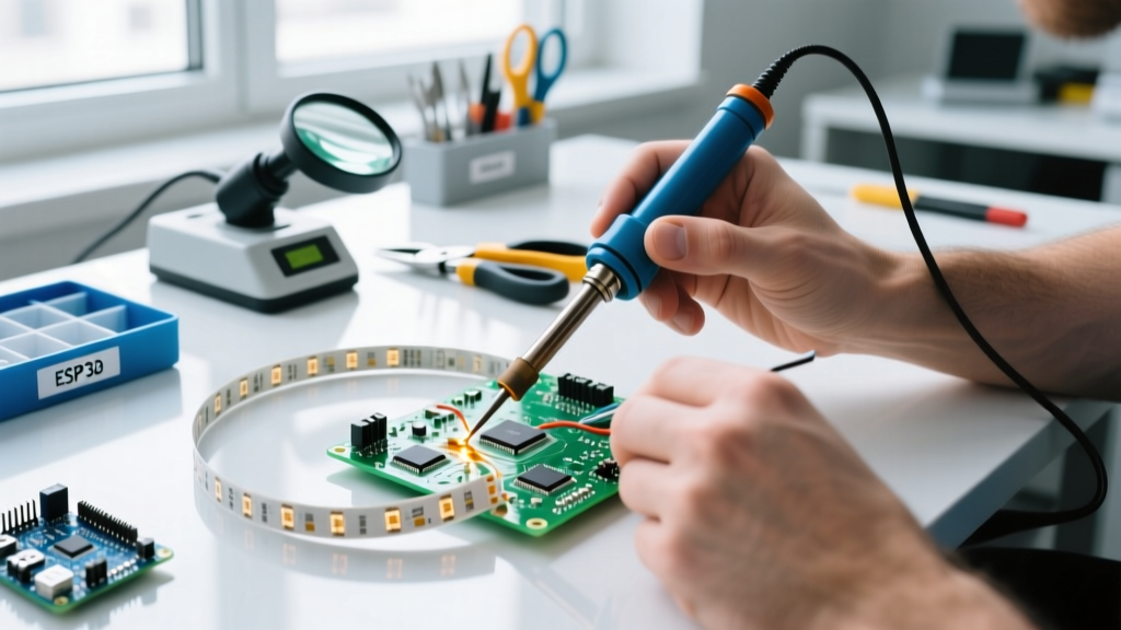
Addressable strips feature tightly spaced copper pads (often just 1.5mm apart). Bridging these pads with solder will short the 5V, Data, and GND lines, potentially destroying the entire strip's microcontroller. Follow this exact sequence to ensure clean, isolated joints.
- Prep the Strip: Cut the strip on the designated scissor line. Use a fiberglass scratch pen or a very fine abrasive to gently polish the copper pads until they shine. This removes oxidation and factory-applied conformal coatings.
- Apply Tacky Flux: Dab a microscopic amount of no-clean flux onto the strip pads using a toothpick or syringe.
- Pre-Tin the Pads: Touch your tinned iron to each pad for exactly 1 second to deposit a small, flat dome of solder. Do not allow the solder to bridge across the gaps.
- Prep the Wires: Strip exactly 3mm of insulation from your 22 AWG silicone wires. Twist the strands tightly and pre-tin them with a thin coat of solder. They should look like solid metal needles, not bulky blobs.
- The Final Join: Hold the pre-tinned wire flush against the pre-tinned pad with tweezers. Apply the iron to the top of the wire. The solder on the wire and the pad will instantly reflow and merge. Remove the iron within 1.5 seconds and hold the wire perfectly still for 3 seconds while the eutectic solder snaps to a solid state.
- Insulation: Slide a piece of 3mm heat-shrink tubing over the joints and apply gentle heat. Avoid resting the heat gun directly on the LED lenses to prevent thermal warping.
Advanced SMD LED Soldering (0805 and 1206 Packages)
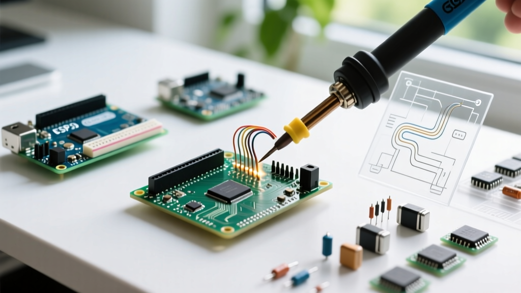
When soldering discrete surface-mount LEDs onto custom PCBs or repairing broken traces, the 'one-pad-first' method is the most reliable approach for hobbyists and professionals alike. As detailed in Adafruit's comprehensive SMD soldering guidelines, managing the component's physical placement is just as critical as the thermal transfer.
The One-Pad-First Technique
Begin by applying a small amount of solder to just one of the PCB pads. Leave the other pad completely clean. Using fine-tipped tweezers, pick up the SMD LED. Note the polarity indicator (usually a green line, a notch, or a larger internal anode structure) and align it correctly.
Slide the LED into position while simultaneously touching the iron to the pre-tinned pad. The solder will melt, and you can gently push the component flat against the PCB. Remove the iron and let the joint solidify. Once anchored, you can release your tweezers. Apply a touch of liquid flux to the remaining pad, touch the iron to it, and feed in a microscopic amount of solder wire to complete the circuit.
Troubleshooting Common LED Soldering Failures
Even with the right gear, environmental and procedural variables can cause defects. Here is how to diagnose and fix the most common issues encountered in the field.
1. Pad Lifting and Delamination
Symptom: The copper pad peels away from the flexible PCB substrate, taking the trace with it. Cause: Excessive dwell time or using a soldering iron temperature that is too low, forcing the user to hold the iron on the pad longer to achieve reflow. Fix: If a pad lifts, do not attempt to glue it back down for high-current applications. Scrape back the flexible silkscreen to expose the underlying copper trace, tin the exposed trace, and solder your wire directly to the trace, using hot glue or UV resin for mechanical strain relief.
2. The 'Dead Pixel' Phenomenon in Addressable Strips
Symptom: The LED you soldered works, but all subsequent LEDs in the chain remain dark or glitch out. Cause: You melted the internal wire-bonds inside the WS2812B IC, or you shorted the Data-In (DIN) to Data-Out (DOUT) pad with a solder bridge. As noted in the NeoPixel Best Practices Guide, the internal data buffer is highly susceptible to thermal and ESD damage. Fix: Inspect the pads under a magnifying lamp. If there is a bridge, use a copper desoldering braid (Goot Wick) with extra flux to gently wick away the excess solder. If the IC is thermally damaged, you must cut out the dead LED and bridge the 5V, GND, and Data lines to the next healthy LED in the chain.
3. Popcorning and Lens Cracking
Symptom: A faint popping sound is heard, and the clear epoxy dome of the LED develops micro-fractures or turns cloudy. Cause: Moisture ingress. If LEDs have been stored in a humid environment, water trapped inside the porous epoxy turns to steam instantly upon contact with 300°C heat, expanding and cracking the housing. Fix: Prevention is the only cure. Store loose SMD LEDs and strips in sealed ESD bags with desiccant packs. If components have been exposed to ambient room humidity for more than 48 hours, bake them on a hotplate at 60°C for two hours before attempting to solder.
Pro-Tip: Strain Relief is Mandatory
Never rely on the solder joint alone to hold a wire to an LED strip. The mechanical leverage of a heavy wire will eventually snap the copper pad off the flexible PCB. Always fold the wire back over the strip and secure it with a dab of neutral-cure silicone RTV sealant or a 3D-printed clip. Avoid cyanoacrylate (Super Glue), as its curing process releases fumes that can permanently fog LED lenses.
Conclusion
Soldering LED components bridges the gap between delicate semiconductor handling and robust electrical assembly. By respecting the strict thermal dwell times, utilizing eutectic 63/37 solder, and employing mechanical strain relief, you ensure that your lighting projects will endure years of operation without suffering from thermal degradation or pad failure. Invest in a quality temperature-controlled station, keep your tips clean, and let the flux do the heavy lifting.