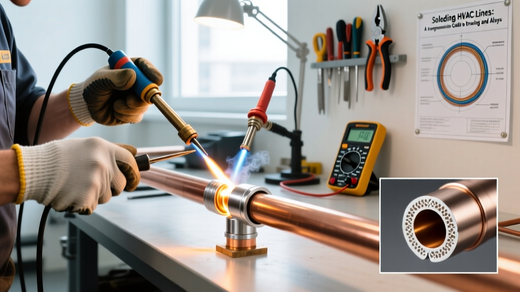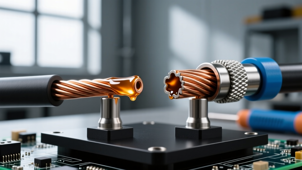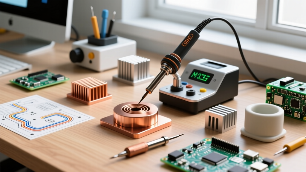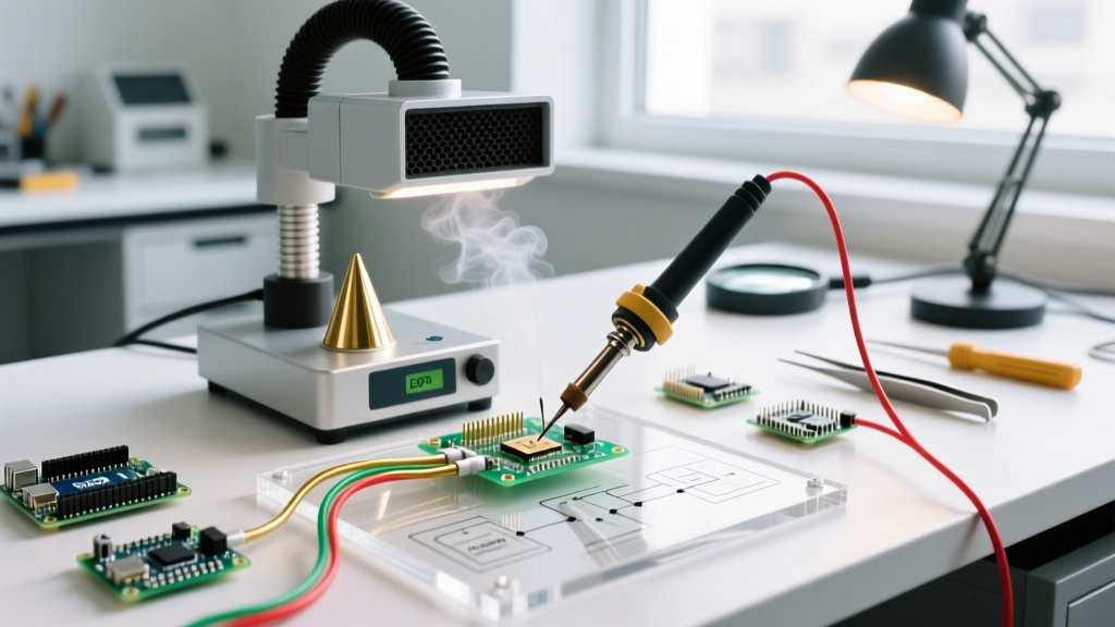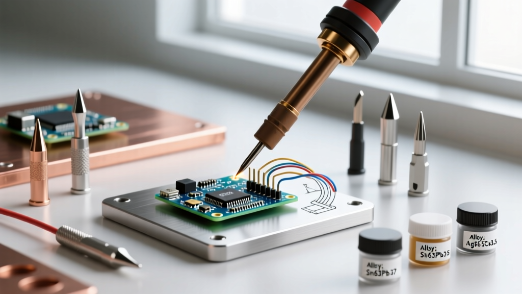

When hobbyists and professionals alike search for the right soldering irn for mixed-material projects, they often overlook the most critical variable: base metal thermal conductivity. A station that perfectly solders a delicate 0402 SMD capacitor will completely fail when attempting to join a heavy-gauge copper wire or a stainless steel chassis tab. Material compatibility in soldering is not just about the alloy you melt; it is about the thermal handshake between your iron's tip geometry, its recovery wattage, and the substrate's heat dissipation rate.
As of 2026, the dominance of lead-free alloys like SAC305 (Tin/Silver/Copper) and the widespread adoption of cartridge-tip technology have fundamentally changed how we approach material-specific soldering. This guide breaks down the exact tip geometries, thermal requirements, and flux chemistries needed for diverse base metals, ensuring reliable metallurgical bonds without destroying your PCB pads or oxidizing your tips.
The Thermal Dynamics of Base Materials
Every metal pulls heat away from your iron at a different rate. If the soldering iron cannot replenish this heat faster than the base material absorbs it, you will experience a 'cold joint'—a brittle, high-resistance connection where the solder fails to form a proper intermetallic compound (IMC). Conversely, if you compensate for high thermal mass by cranking the temperature to 420°C, you risk delaminating FR4 fiberglass and destroying sensitive silicon dies.
Expert Insight: The goal is never to use the highest possible temperature. The goal is to use the highest possible thermal mass and recovery rate at the lowest effective temperature. According to the IPC J-STD-001 standards, excessive dwell times and temperatures directly correlate to pad lift and barrel cracking in plated through-holes.
Soldering Iron Tip Selection by Material Matrix
Selecting the correct tip geometry ensures maximum surface area contact, which drastically improves thermal transfer. Below is a compatibility matrix for common base materials when using standard SAC305 lead-free solder.
| Base Material | Thermal Conductivity (W/m·K) | Recommended Tip Geometry | Target Temp (SAC305) | IPC Flux Classification |
|---|---|---|---|---|
| Copper (Bare/ENIG) | 385 | Chisel (e.g., Hakko T18-D24) | 340°C - 350°C | ROL0 / ROL1 |
| Brass | 109 | Bevel / Hoof | 350°C - 360°C | ROL1 |
| Stainless Steel | 16 | Heavy Spoon / Spatula | 380°C+ | ORH1 (Post-wash required) |
| Nickel | 90 | Chisel / Conical | 360°C - 370°C | ROL1 / REL0 |
| Aluminum | 205 | Ultrasonic / Specialized | N/A (Requires Zn-based) | Specialized Al Flux |
Deep Dive: Soldering Difficult Metals
Stainless Steel & Nickel (The Oxide Barrier)
Stainless steel and nickel are notoriously difficult to solder because they form a rapid, impenetrable chromium/nickel oxide layer when heated. Standard rosin-based fluxes (ROL0) are entirely ineffective here. To achieve a bond, you must use an Organic, High-activity flux with halides (classified as ORH1 under IPC J-STD-004).
- Tip Selection: Use a heavy spoon or spatula tip (like the JBC C245-945). The concave shape holds a large solder puddle, enveloping the joint and excluding oxygen while the aggressive flux etches the oxide layer.
- Warning: ORH1 fluxes are highly corrosive. You must clean the joint with isopropyl alcohol or a dedicated saponifier immediately after cooling, or the residual halides will cause severe galvanic corrosion over time.
Aluminum (The Gallium & Flux Challenge)
Standard tin-lead or SAC alloys will not wet aluminum due to its tough aluminum oxide skin, which reforms in milliseconds upon exposure to air. While specialized zinc-based solders and aggressive fluoride fluxes exist, the most reliable method in 2026 for DIY and prototyping is ultrasonic soldering. Ultrasonic irons use high-frequency acoustic vibrations to cavitate the molten solder, physically shattering the oxide layer and allowing the zinc-tin alloy to bond directly to the bare aluminum substrate without chemical flux.
Wattage and Cartridge Technology in 2026
The era of ceramic heating elements separated from the tip by an air gap is largely over for professional and serious DIY work. Modern cartridge systems integrate the heating element and thermocouple directly behind the tip face.
- Hakko FX-951 (~$280): Utilizes T21 cartridges. Excellent for standard PCB work and moderate ground planes, offering 70W of rapid recovery.
- Weller WE1010 (~$110): A budget-friendly 70W station using ET tips. Good for general hobbyist through-hole work, but struggles with heavy copper thermal mass.
- JBC CD-2BQE (~$650): The industry benchmark. Uses C245 cartridges and delivers up to 130W. The thermocouple is located less than 1mm from the tip surface, allowing it to detect a temperature drop and inject current in under 0.5 seconds. This is mandatory for soldering large copper pours without cranking the dial to damaging temperatures.
Flux Chemistry and Material Pairing
According to the Weller Soldering Knowledge Base, matching your flux to the material is just as vital as the iron itself. The IPC classifies fluxes by material (Rosin, Resin, Organic, Inorganic) and activity level.
- ROL0 (Rosin, Low Activity, No Halides): The standard for bare copper, ENIG, and HASL PCBs. Safe to leave on the board (no-clean).
- REL1 (Resin, Low Activity, Halides): Better for slightly oxidized brass or nickel-plated connectors. Requires cleaning in high-reliability aerospace/medical builds.
- ORH1 (Organic, High Activity, Halides): Water-soluble acids designed for stainless steel, nichrome, and heavily oxidized chassis grounds. Never use on standard PCBs unless you have a rigorous ultrasonic cleaning process.
Common Failure Modes & Edge Cases
1. FR4 Pad Delamination
Standard FR4 PCB material has a Glass Transition Temperature (Tg) of roughly 130°C to 140°C (or 170°C for high-Tg variants). If you use a low-wattage iron and hold it on a pad for 6+ seconds trying to get the solder to flow, the localized heat will exceed the epoxy's breakdown threshold. The copper pad will lift off the fiberglass substrate, permanently ruining the board. Solution: Use a higher thermal mass tip (not a higher temperature) and limit dwell time to under 3 seconds.
2. Lead-Free Tip Pitting
SAC305 solder, combined with the aggressive activators in modern water-soluble fluxes, will literally eat the iron plating off standard copper tips, leaving a pitted, unwettable crater. If you are exclusively soldering lead-free on heavy materials, invest in specialized 'lead-free' tip variants (such as Weller's RT-MS series or Hakko's T18 'D' series with reinforced plating), which feature a thicker iron layer to resist chemical erosion.
3. The 'Cold Joint' Illusion on Brass
Brass contains zinc, which can vaporize and create a porous, dull-looking joint that mimics a cold joint, even when the metallurgical bond is sound. When soldering brass terminals (like XT60 connectors or automotive spades), use a slight excess of ROL1 flux and allow the joint to cool naturally without blowing on it, which can cause micro-fractures in the crystalline structure.
Frequently Asked Questions
Can I use a standard soldering iron to solder aluminum wires?
No. Standard irons and tin-based solders will not bond to aluminum. You must use a specialized zinc-based aluminum solder (like Alumilite) with a dedicated aluminum flux, or an ultrasonic soldering iron to break the oxide layer mechanically.
Why does my tip turn black and refuse to melt solder on steel?
Stainless steel requires high heat (380°C+) and aggressive fluxes. At these temperatures, standard rosin flux carbonizes instantly, baking a hard black crust onto the tip's iron plating. This acts as a thermal insulator. You must clean the tip using a brass wire sponge and specialized tip tinner (which contains mild abrasives and fresh solder) to restore the wettable surface.
Is a 40W iron enough for soldering 12 AWG silicone wire?
A 40W iron will struggle immensely with 12 AWG wire due to the copper's massive thermal conductivity. The wire will act as a heatsink, pulling heat away faster than the iron can generate it, resulting in a cold, brittle joint. For wires thicker than 16 AWG, a minimum of 70W (preferably 100W+ cartridge system) and a heavy chisel or bevel tip is required.