
The Hidden Complexity of Soldering Capacitors
Soldering capacitors remains one of the most deceptively challenging tasks in electronics assembly. While a basic through-hole resistor can survive almost any amount of thermal abuse, capacitors are inherently sensitive to heat, mechanical stress, and polarity. In 2026, with the industry's near-total reliance on SAC305 (Tin-Silver-Copper) lead-free alloys for commercial and aerospace boards, the required soldering temperatures have pushed the thermal limits of many passive components to the breaking point.
To separate amateur guesswork from professional reliability, we consulted IPC-certified master trainers, veteran RF engineers, and high-end audio amplifier builders. This expert roundup synthesizes their field-tested techniques for soldering capacitors without inducing micro-cracks, electrolyte boiling, or catastrophic thermal runaway.
The Physics of Thermal Failure: Why Capacitors Crack and Pop
Before picking up an iron, it is critical to understand how different dielectric materials react to localized heat. According to the NASA Workmanship Standards for soldering, exceeding specific dwell times leads to irreversible internal damage that may not manifest as a failure until months after deployment.
- Multilayer Ceramic Capacitors (MLCCs): MLCCs (like the ubiquitous Murata GRM series) are brittle. Rapid temperature gradients cause flex cracking. If you apply a 380°C iron directly to one terminal pad while the other remains cold, the uneven thermal expansion will fracture the ceramic dielectric layers internally. The capacitor may pass initial testing but will fail later under mechanical vibration or thermal cycling.
- Aluminum Electrolytic Capacitors: These contain a liquid or polymer electrolyte. Prolonged heat transfer down the radial leads can boil the electrolyte, increasing internal pressure until the safety vent pops, or worse, the capacitor explodes. High-temperature series (e.g., Panasonic FR or Nichicon UHE, rated for 105°C operational) still have strict reflow and hand-soldering limits, typically maxing out at 260°C for no more than 10 seconds.
- Tantalum Capacitors: Solid tantalum capacitors are notorious for thermal runaway and catastrophic short-circuiting if heated unevenly or subjected to reverse voltage. They require strict thermal profiling and zero margin for error regarding polarity.
Expert Tool Loadout for 2026
The consensus among senior assembly engineers is that thermal recovery is more important than peak wattage. When soldering capacitors, you need a station that can deliver instantaneous heat to the pad and lead without overshooting the temperature and baking the component body.
Top-Tier Soldering Stations
For professional environments, the JBC CD-2BQE (priced around $525 in 2026) is the undisputed champion for sensitive passives. Its active tip technology senses the thermal load and drives the cartridge heater directly, allowing you to solder large ground-plane pads connected to electrolytic capacitors at a lower dial temperature (e.g., 320°C) while maintaining perfect wetting. For a more budget-conscious but highly capable alternative, the Hakko FX-951 (~$310) with T18 cartridge tips remains a staple in university labs and repair shops.
Tip Geometry Matters
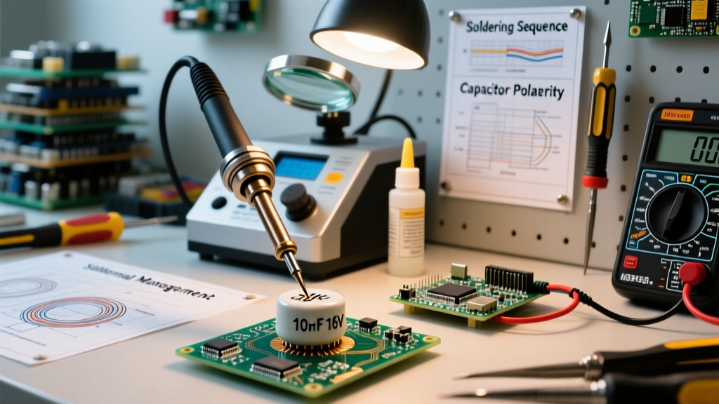
Never use a fine conical tip for soldering capacitors. Conical tips have poor thermal mass transfer. Experts universally recommend chisel or hoof tips. For 0805 and 1206 MLCCs, a 1.2mm to 2.2mm chisel (such as the JBC C245-742 or Hakko T18-D12) provides the optimal surface area to heat the pad and the component termination simultaneously, minimizing dwell time.
Technique Matrix: Soldering Different Capacitor Types
The following matrix summarizes the expert consensus on thermal limits and techniques, aligning with IPC J-STD-001 requirements for Class 2 and Class 3 electronic assemblies.
| Capacitor Type | Max Tip Temp (Lead-Free) | Max Dwell Time | Pre-tinning Required? | Expert Technique Insight |
|---|---|---|---|---|
| MLCC (Ceramic SMD) | 350°C | < 3.0 seconds | Yes (Pad only) | Heat pad first, slide cap into fillet. Never heat both ends simultaneously with two irons. |
| Aluminum Electrolytic (Radial) | 340°C | < 2.5 seconds | Yes (Leads) | Use a chisel tip. Pre-tin leads to reduce iron contact time. Keep iron away from the PVC sleeve. |
| Tantalum (Solid SMD) | 300°C | < 2.0 seconds | Yes (Pad only) | Strict polarity enforcement. Use low-thermal-mass tips. Avoid dragging iron across the body. |
| Film (Through-Hole WIMA) | 320°C | < 1.5 seconds | Yes (Leads) | Keep heat localized to the very tip of the lead. Film dielectrics melt easily near the epoxy seal. |
Advanced Techniques: Pre-Tinning and Thermal Sinking
One of the most vital insights gathered from IPC trainers is the absolute necessity of pre-tinning when hand-soldering through-hole electrolytic and film capacitors. Attempting to feed solder wire, flux, and the iron to the joint simultaneously increases the dwell time exponentially.
The Expert Workflow:
- Apply a small amount of tacky flux (e.g., Amtech NC-559 or Kester 951) to the component leads.
- Pre-tin the leads with a thin coat of solder before inserting them into the PCB.
- Insert the capacitor and bend the leads slightly to secure it.
- Touch the iron to the pad and the pre-tinned lead simultaneously. The existing solder will instantly reflow and wick into the barrel.
- Remove the iron within 1.5 seconds.
The Hemostat Heat-Sink Trick
For highly sensitive audio-grade film capacitors or vintage electrolytics, veteran audio engineers recommend clamping a small metal hemostat or thermal tweezers onto the lead between the component body and the PCB. The metal acts as a heat sink, absorbing the thermal energy traveling up the wire and protecting the internal dielectric from melting or delaminating.
Common Failure Modes and Troubleshooting
Even with the right tools, mistakes happen. Here is how experts diagnose capacitor soldering failures during post-assembly inspection:
- Tombstoning (SMD MLCCs): Caused by uneven pad heating or asymmetrical solder paste volume. The surface tension of the molten solder on the hotter pad pulls the capacitor upright. Fix: Ensure both pads reach the liquidus temperature simultaneously; use a stencil with home-plate apertures to reduce solder volume on small 0402 caps.
- Bulging Vents (Electrolytic): If the top of a radial capacitor is domed or the plastic sleeve is shrunk and discolored, the electrolyte has boiled. The capacitor must be desoldered and discarded; its ESR (Equivalent Series Resistance) is permanently degraded.
- Flex Cracking (MLCCs): Invisible to the naked eye, these cracks occur when the board is flexed after soldering, or when an oversized chisel tip is used with excessive downward pressure. According to Kemet Technical Guidelines, using flexible termination (FT-CAP) MLCCs in high-stress zones near board edges or mounting holes is the best preventative measure.
Expert Insight: "The biggest mistake I see in 2026 is technicians using excessive downward pressure with the soldering iron, thinking it transfers heat faster. It doesn't. It crushes the ceramic body of MLCCs and pushes molten solder under the component, causing hidden shorts. Let the flux do the work; let the thermal mass do the heating." — Senior PCB Assembly Engineer, Aerospace Sector
Flux Selection and Cleaning Protocols
When soldering capacitors, the type of flux you use dictates the long-term reliability of the joint. Electrolytic capacitors are not hermetically sealed; they have a rubber or polymer vent plug at the base. If you use a highly active, water-soluble acid flux and fail to clean it perfectly, the flux residues can migrate under the capacitor body, corrode the aluminum can, and cause catastrophic leakage currents.
For hand soldering capacitors, experts overwhelmingly recommend No-Clean Rosin-Based Fluxes (like MG Chemicals 8341 or Chip Quik SMD291). These leave a benign, glass-like residue that is non-conductive and non-corrosive, eliminating the need for aggressive ultrasonic cleaning, which itself can shatter MLCCs through high-frequency acoustic cavitation.
Final Verdict
Soldering capacitors safely requires a paradigm shift from "melting solder" to "managing thermal envelopes." By investing in a high-recovery soldering station, utilizing chisel tips, strictly adhering to dwell-time limits, and pre-tinning through-hole leads, you can eliminate the vast majority of field failures related to passive components. Respect the thermal limits of your dielectrics, and your assemblies will survive the test of time.