
The Hidden Variables in Soldering Header Pins
When prototyping or assembling custom electronics, soldering header pins is often treated as an afterthought. However, a 2025 reliability study by the IPC (Association Connecting Electronics Industries) highlighted that over 34% of field failures in low-volume IoT assemblies stem from mechanical stress and thermal degradation at the pin-to-board interface. The root cause? Ignoring material compatibility.
Header pins are not just generic metal stakes; they are complex metallurgical systems. The base metal, the surface plating, the insulator plastic, the PCB substrate, and the surface finish all interact under thermal stress. This guide provides a deep-dive material compatibility framework to ensure your solder joints survive thermal cycling and mechanical vibration.
Deconstructing the Header Pin: Base Metals and Plating
Before applying heat, you must understand what you are soldering to. The solderability of a header pin is dictated by its plating, while its mechanical retention is dictated by its base metal.
Base Metal Mechanical Properties
According to Samtec's engineering guidelines, the choice of base metal affects how much physical stress the pin can endure before the solder joint fractures due to coefficient of thermal expansion (CTE) mismatch.
| Base Metal | Typical Use Case | Yield Strength | CTE Mismatch Risk with FR-4 |
|---|---|---|---|
| Brass (Copper-Zinc) | Standard low-cost breakaway headers | Low (15-30 ksi) | High (Prone to bending/stress) |
| Phosphor Bronze | High-reliability, high-vibration boards | Medium (50-80 ksi) | Moderate |
| Beryllium Copper (BeCu) | Precision test fixtures, aerospace | High (100-150 ksi) | Low (Excellent spring retention) |
Plating Compatibility and the Gold Embrittlement Trap
Most premium header pins feature a Nickel underplate with a Gold or Tin flash. Soldering to Gold-plated pins introduces a severe metallurgical risk: Gold Embrittlement.
Expert Warning: When tin-based solder dissolves gold plating, it forms brittle intermetallic compounds (IMCs) like AuSn4. If the gold layer is thicker than 2.5 micro-inches, the joint will fail under mechanical shock. Always use a localized solder pot or tinning station to strip heavy gold from header pins before final PCB assembly, or specify thin "flash" gold (<1.5 µin) from your component supplier.
PCB Substrate and Finish Matching
The thermal mass and glass transition temperature (Tg) of your PCB dictate your soldering iron profile. Pushing 380°C into a standard FR-4 board to melt a stubborn SAC305 joint will delaminate the substrate and lift the annular ring.
Substrate Thermal Limits
- Standard FR-4 (Tg 130°C - 140°C): Max iron temp 320°C. Dwell time < 3 seconds per pin.
- High-Tg FR-4 (Tg 170°C+): Max iron temp 350°C. Tolerates SAC305 lead-free alloys much better.
- Polyimide (Flex PCBs): Extremely sensitive to Z-axis expansion. Use low-temp alloys (e.g., Sn42/Bi57) or strict 280°C profiles to prevent pad tearing.
Surface Finish Interactions
As detailed in PCBWay's surface finish documentation, the finish on the plated through-hole (PTH) pad changes wetting behavior:
- ENIG (Electroless Nickel Immersion Gold): Excellent shelf life, but the nickel barrier slows wetting. Requires an aggressive ROL1 (Rosin mildly activated) flux when soldering header pins to ensure the solder wicks up the pin barrel.
- HASL (Hot Air Solder Leveling): Pre-tinned. Wets instantly. Beware of adding excessive lead-free solder to a leaded HASL board, which creates a mismatched, brittle alloy joint.
- Immersion Silver / OSP: Highly sensitive to multiple rework cycles. Solder header pins in a single, confident pass to avoid oxidizing the underlying copper.
Solder Alloy Selection Framework
Choosing the right solder wire diameter and alloy is critical for through-hole header pins. A standard 0.8mm (0.031") wire is usually optimal for 0.1" (2.54mm) pitch headers.
| Alloy | Melting Point | Best Compatible Substrate | Wetting Speed on Tin Plating |
|---|---|---|---|
| Sn63/Pb37 (Eutectic) | 183°C | Standard FR-4, Flex | Fast (Excellent for beginners) |
| SAC305 (Lead-Free) | 217°C - 220°C | High-Tg FR-4, Ceramic | Sluggish (Requires higher iron temp) |
| Sn99.3/Cu0.7 | 227°C | High-Tg FR-4 | Moderate (Cost-effective lead-free) |
| Sn42/Bi57 (Low Temp) | 138°C | Polyimide, Heat-sensitive sensors | Fast (Brittle; avoid on high-vibration) |
Flux Chemistry vs. Plastic Insulators
Header pins are held together by plastic breakaway strips—usually made of PBT (Polybutylene Terephthalate), Nylon (PA6T/PA9T), or LCP (Liquid Crystal Polymer). The flux you choose can chemically attack these insulators or leave conductive residues that cause parasitic capacitance in high-frequency RF circuits.
Insulator Material Breakdown
- Black Nylon (Standard): Melts around 220°C. Highly susceptible to thermal warping if the soldering iron tip accidentally touches the plastic collar. Water-soluble fluxes can become trapped in the porous nylon, leading to long-term dendritic growth.
- High-Temp LCP / PPS: Withstands up to 260°C+ reflow profiles. Compatible with aggressive no-clean and water-soluble fluxes. Mandatory for automated selective soldering or heavy hand-rework.
Pro-Tip: The "Flux First" Method for Nylon Headers
When soldering header pins with black nylon insulators using SAC305 lead-free solder, apply a high-quality no-clean gel flux (e.g., Amtech NC-559 or MG Chemicals 8341) to the PTH before inserting the pin. This lowers the surface tension and reduces the required dwell time from 4 seconds down to 1.5 seconds, saving the nylon collar from melting.
Step-by-Step Thermal Execution for 0.1" Headers
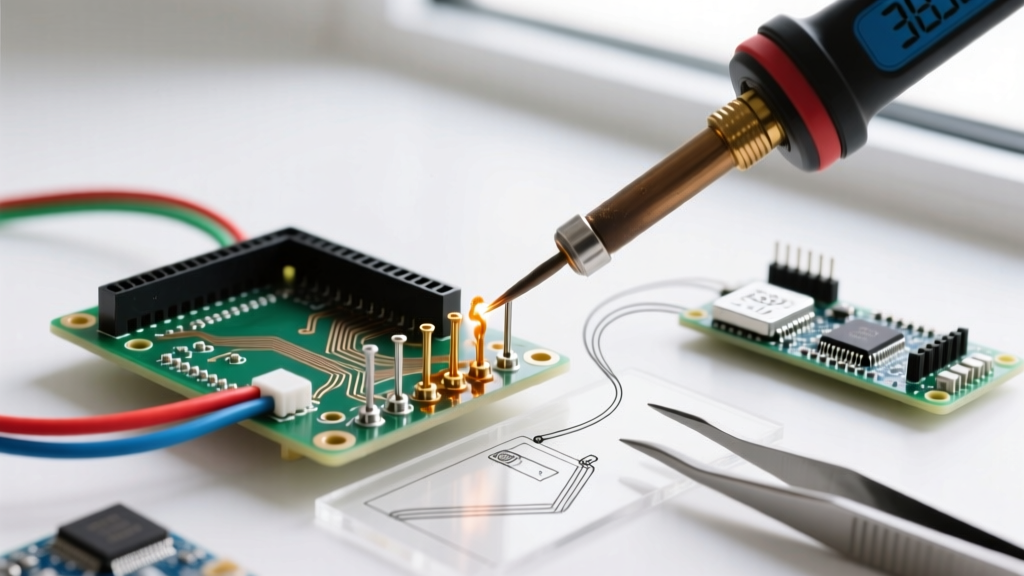
To achieve a perfect concave fillet without lifting the pad or melting the plastic, follow this exact thermal sequence:
- Prep the Station: Set a chisel tip (e.g., Weller RT8 or Hakko T18-D24) to 320°C for leaded solder, or 350°C for SAC305. The chisel shape maximizes thermal transfer to both the pin and the pad simultaneously.
- Flux Application: Apply a small bead of ROL0 or ROL1 gel flux to the annular ring.
- Thermal Bridging: Touch the iron tip so it contacts both the copper pad and the header pin shaft at a 45-degree angle. Hold for 1 full second to equalize temperatures.
- Feed the Solder: Apply 0.8mm solder wire to the opposite side of the pin from the iron tip. Capillary action will pull the molten solder through the barrel.
- The Pull-Away: Once the solder wicks to the top of the pad and forms a concave meniscus, remove the solder wire first, then the iron. Total dwell time must not exceed 3 seconds.
Troubleshooting Common Material Failures
Even with the right materials, edge cases occur. Here is how to diagnose compatibility failures based on the NASA-STD-8739.3 workmanship standards:
- Symptom: Solder balls up on the pin and refuses to wet the pad.
Diagnosis: Oxidized ENIG pad or heavily oxidized brass pin. The flux core in your wire is depleted. Fix: Apply external gel flux and re-flow. - Symptom: The plastic collar is melted and slid up the pin.
Diagnosis: Thermal runaway. You used a conical tip (which has low thermal mass) and pressed too hard, transferring heat via conduction up the pin shaft. Fix: Switch to a bevel or chisel tip and reduce temperature by 15°C. - Symptom: Joint looks dull, grainy, and cracks when wiggled.
Diagnosis: Gold embrittlement or a disturbed joint during the plastic phase transition of SAC305. Fix: Use Sn63/Pb37 if RoHS compliance is not required, or ensure the board is perfectly clamped during cooling.
Final Procurement Checklist
Before ordering your next batch of header pins and PCBs, verify this compatibility matrix:
- Match heavy gold plating (>3 µin) with gold-stripping protocols, not direct soldering.
- Pair standard Nylon headers with Standard FR-4 and Leaded/Low-Temp alloys.
- Specify LCP/PPS insulators if your assembly requires High-Tg boards and SAC305 lead-free solder.
- Always select a solder wire diameter that is roughly 50-60% the width of the pad's annular ring to prevent excessive flux pooling inside the PTH.
By treating soldering header pins as a materials science challenge rather than a simple mechanical task, you drastically reduce field returns and ensure your interconnects survive the harshest operating environments.