
The Core Metallurgical Divide: Melting the Base vs. Melting the Filler
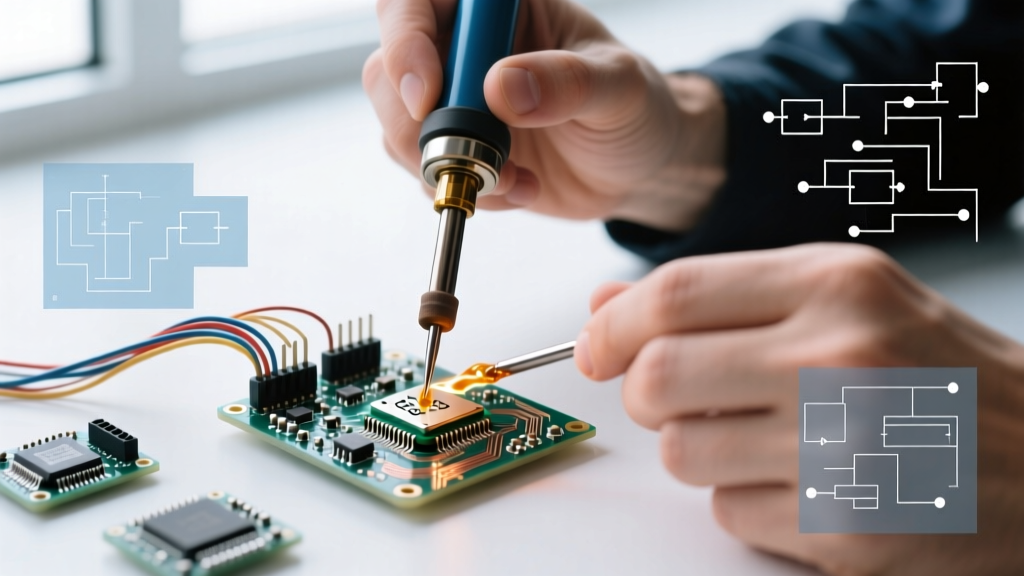
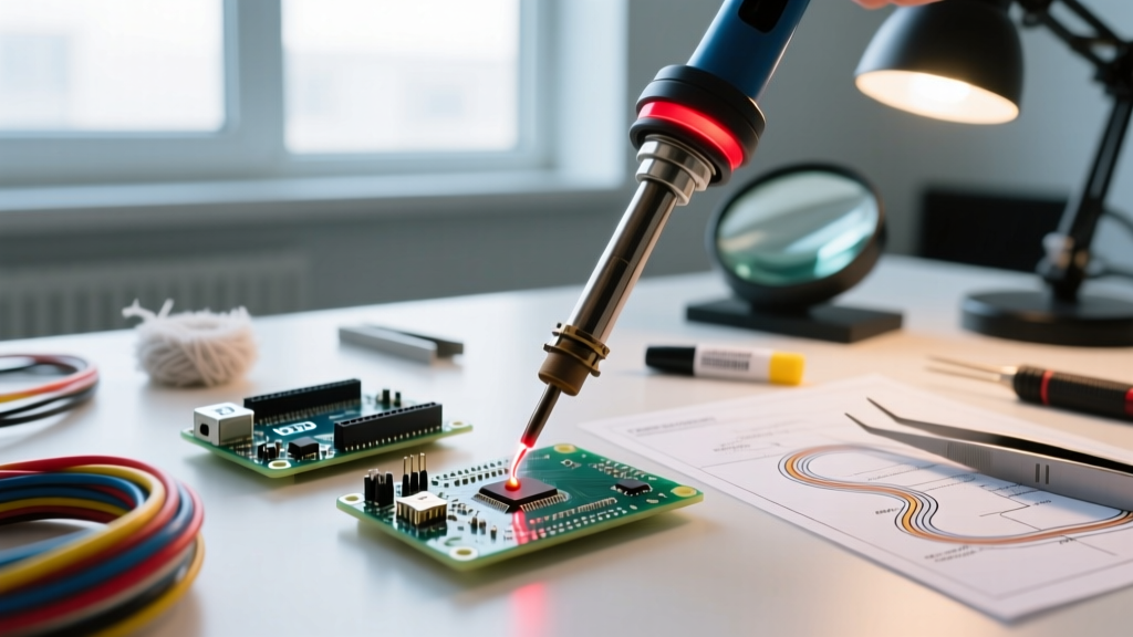
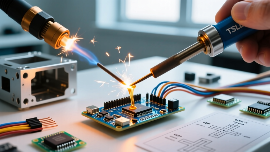
When makers and engineers ask us what is the difference between welding and soldering, the answer fundamentally comes down to the state of the base metal during the joining process. In welding, the base metals being joined are melted and fused together, often with the addition of a filler material. In soldering, the base metal remains entirely solid; only the filler metal (the solder alloy) is melted, relying on capillary action and the formation of an intermetallic compound (IMC) to create a bond.
This metallurgical distinction dictates everything from the thermal profiles required to the mechanical strength of the final joint. For instance, when TIG welding mild steel, the arc temperature exceeds 3,000°C, melting the steel workpieces (which melt around 1,370°C) and an ER70S-6 filler rod. Conversely, when assembling a printed circuit board (PCB), the copper traces (melting point 1,085°C) must never liquefy. Instead, a SAC305 (96.5% Sn, 3.0% Ag, 0.5% Cu) lead-free solder alloy is used, which melts at a much lower 217°C to 220°C, forming a microscopic Cu6Sn5 intermetallic layer with the copper pad without compromising the FR4 substrate.
Thermal & Mechanical Comparison Matrix
| Process | Base Metal State | Typical Temperature Range | Primary Bonding Mechanism | Common Applications |
|---|---|---|---|---|
| Soldering | Solid | 183°C - 450°C (361°F - 842°F) | Intermetallic Compound (IMC) / Capillary Action | PCBs, microelectronics, copper plumbing, jewelry |
| Brazing | Solid | 450°C - 1,200°C (842°F - 2,192°F) | Capillary Action / Alloy Diffusion | HVAC refrigeration lines, carbide tool tipping, aerospace |
| Welding (TIG/MIG/SMAW) | Melted (Liquid) | 1,500°C - 3,500°C+ (2,732°F - 6,332°F+) | Coalescence / Fusion of Base Metals | Structural steel, automotive chassis, pipelines, shipbuilding |
| Resistance Spot Welding | Melted (Localized) | Variable (Joule Heating to Melting Point) | Localized Fusion via Electrical Resistance | Battery tabs (18650/21700), automotive body panels |
Troubleshooting Joint Failures: Did You Choose the Wrong Process?
A significant percentage of DIY project failures stem from misapplying soldering to structural applications, or attempting to weld materials that require low-thermal-impact joining. Understanding the failure modes of each process is critical for troubleshooting.
Mechanical Stress Failures: The Solder Creep Phenomenon
Solder alloys, particularly tin-lead (Sn63/Pb37) and standard lead-free variants, have a very low homologous temperature. This means that even at standard room temperature (25°C), solder is operating at roughly 60% to 70% of its absolute melting point. Under constant mechanical tensile or shear load, solder will undergo 'creep'—a slow, continuous plastic deformation that eventually leads to joint fracture.
Expert Troubleshooting Tip: If a soldered chassis bracket or robotic arm joint is slowly pulling apart over weeks or months, you are experiencing solder creep. Solder provides excellent electrical conductivity and shear strength against sudden impacts, but near-zero tensile strength under constant load. You must switch to mechanical fasteners (screws/rivets) or MIG/TIG welding for continuous structural load-bearing joints.
Electrical Resistance and Thermal Runaway
Conversely, attempting to use welding processes on microelectronics or battery cells introduces catastrophic thermal damage. When building custom lithium-ion battery packs using 21700 or 4680 cells, some beginners attempt to solder pure nickel strips directly to the cell terminals using high-wattage irons (e.g., Hakko FX-951 or Weller WE1010 set to 400°C). Because nickel has high thermal conductivity and the cell casing acts as a massive heat sink, the solder often fails to wet properly, resulting in a 'cold joint.' Worse, the prolonged heat transfer penetrates the cell's top seal, degrading the internal polymer separator and triggering thermal runaway. According to safety guidelines outlined by the Occupational Safety and Health Administration (OSHA), improper battery assembly poses severe fire and toxic fume hazards. The correct method is resistance spot welding, which localizes the fusion to the nickel-to-steel interface in milliseconds, keeping the internal cell jellyroll completely cool.
FAQ: Answering Common Welding vs. Soldering Questions
1. Is 'Silver Soldering' actually welding?
No. The term 'silver soldering' is a colloquial misnomer that actually refers to silver brazing. True soldering is defined by the American Welding Society (AWS) as a process occurring below 450°C (842°F). Silver-bearing alloys (like BAg-24, which is 50% Ag, 34% Cu, 16% Zn) melt between 630°C and 705°C. Because the temperature exceeds the 450°C threshold, this is technically brazing. The base metal remains solid, but the joint achieves vastly higher tensile strength than standard tin-based solder, making it ideal for high-pressure refrigeration lines and structural jewelry.
2. Can I use a micro-TIG welder to repair a broken PCB trace?
While micro-TIG and laser welding are used in specialized industrial PCB repair (such as fixing heavy copper busbars in power inverters), they are entirely unsuitable for standard FR4 trace repair. The copper trace will vaporize or ball up before a stable weld pool can form, and the surrounding epoxy-glass FR4 substrate will instantly carbonize and burn at temperatures exceeding 300°C. For standard PCB trace repair, the IPC-A-610 standard mandates the use of copper foil tape, conductive epoxy, or traditional solder jumper wires using a precision micro-soldering iron with a chisel tip and Sn63/Pb37 or SAC305 wire.
3. Why do we use flux in soldering but shielding gas in welding?
Both serve the exact same metallurgical purpose: preventing oxidation. When metal is heated, it rapidly reacts with oxygen in the atmosphere to form an oxide layer (e.g., copper oxide or iron oxide), which prevents the filler metal from wetting and bonding. In soldering, chemical fluxes (like rosin-based RMA or water-soluble organic acids) are applied to dissolve these oxides at low temperatures. In welding, the temperatures are so extreme that chemical fluxes would vaporize instantly; therefore, inert shielding gases like Argon or CO2 (in MIG/TIG processes) are used to physically displace the oxygen from the weld puddle. The American Welding Society (AWS) provides extensive documentation on shielding gas flow rates and oxide prevention in their structural welding codes.
Industry Standards and Final Takeaways
Ultimately, the choice between welding and soldering is not about which process is 'stronger,' but which process aligns with the thermal limits and operational requirements of your base materials. For structural integrity, high-temperature environments, and heavy mechanical loads, welding and brazing are mandatory. For delicate electrical connections, micro-mechanical assembly, and thermal-sensitive components, soldering is the only viable option.
Before beginning any project, consult the relevant industry standards. For electronic assemblies, adherence to IPC (Association Connecting Electronics Industries) standards ensures reliable intermetallic bonding and long-term joint reliability. For structural metalwork, AWS codes dictate the necessary penetration, filler matching, and thermal management required to prevent catastrophic joint failure.