
The Architecture of High-Current DC Connections
Whether you are building a 52V e-bike battery pack, wiring a 12S LiPo for a heavy-lift drone, or configuring an off-grid solar charge controller, the integrity of your DC power delivery hinges on your interconnects. Specifically, soldering bullet connectors (often referred to as banana plugs or gold bullets) remains the gold standard for hobbyists and custom fabricators. However, the margin for error is razor-thin. A poorly executed joint can introduce milliohms of parasitic resistance, leading to localized heating, severe voltage sag, and in extreme cases, thermal runaway.
This decision framework provides a rigorous, engineering-minded approach to selecting, sizing, and executing bullet connector solder joints in 2026, moving beyond basic tutorials into the realm of reliable power electronics assembly.
The Primary Decision: Solder vs. Crimp for Bullet Connectors
Before picking up an iron, you must validate whether soldering is the correct assembly method for your specific use case. While crimping is the undisputed king of high-vibration automotive and aerospace environments, soldering dominates in high-current DC hobbyist spaces due to space constraints and tooling accessibility.
| Parameter | Soldering Bullet Connectors | Crimping Bullet Connectors |
|---|---|---|
| Tooling Cost | Low to Medium ($30 - $150 for quality station) | High ($150 - $400 for proper ratcheting crimpers & dies) |
| Space/Weight | Compact; minimal added bulk | Bulky; requires large crimp barrels |
| Vibration Resistance | Moderate (prone to fatigue if wire flexes at joint) | Exceptional (cold-weld gas-tight seal) |
| Best Use Case | RC models, e-bikes, solar, custom enclosures | Automotive harnesses, industrial machinery |
Expert Rule of Thumb: If the wire will experience continuous high-frequency vibration (e.g., mounted directly to an unsuspended motor), crimp it. If the wire is routed through a chassis or secured with zip-ties within 2 inches of the connector, soldering bullet connectors is the superior, more compact choice.
Sizing Framework: Matching Bullet Diameter to AWG and Current
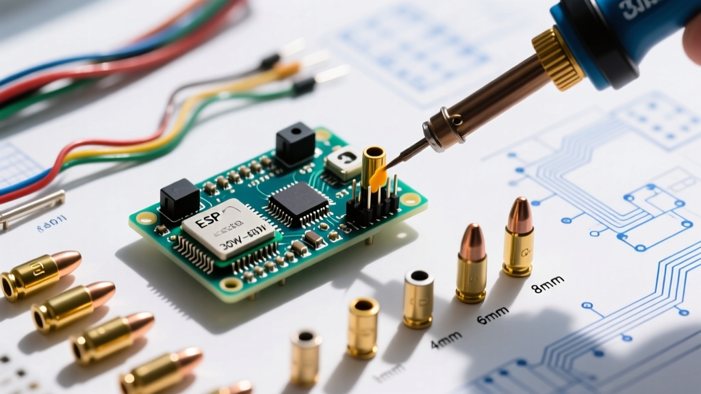
Selecting the wrong bullet size for your wire gauge is a primary cause of assembly failure. A 4mm bullet soldered to 8 AWG wire will result in a mechanically weak joint and excessive resistance. Use this matrix to align your components:
| Connector Size | Optimal Wire Gauge (AWG) | Continuous Current Rating | Common Applications |
|---|---|---|---|
| 2.0mm | 18 - 16 AWG | 20A | Small servos, low-power ESCs |
| 3.5mm | 16 - 14 AWG | 60A | 1/10th scale RC cars, drone motors |
| 4.0mm | 14 - 12 AWG | 85A | XT60 equivalents, mid-size solar |
| 5.5mm | 12 - 10 AWG | 130A | XT90 equivalents, e-skateboards |
| 6.0mm | 10 - 8 AWG | 150A | Heavy-lift drones, 48V battery banks |
| 8.0mm | 8 - 6 AWG | 200A+ | EV conversions, massive inverters |
Thermal Mass & Tooling: Selecting the Right Soldering Station
The most common failure mode when soldering bullet connectors is the cold joint. This occurs when an underpowered iron fails to overcome the thermal mass of heavy-gauge copper wire and the brass/gold-plated connector shell. The wire acts as a massive heatsink, pulling heat away from the solder joint.
Wattage and Tip Geometry
Forget the 30W craft-store irons. For 4mm to 6mm bullet connectors, you need a minimum of 65W to 100W of recoverable thermal power. In 2026, the Pinecil V2 (retailing around $28) or the Hakko FX-951 (around $250) are the benchmark stations.
- Tip Shape: Never use a conical (pointed) tip. The surface area contact is too small. Use a large chisel tip (e.g., Hakko T12-D24 or Pinecil D24) or a bevel tip to maximize thermal transfer to the curved brass shell of the bullet.
- Temperature: Set your station to 380°C - 400°C (715°F - 750°F). You want high heat for a short duration (3-5 seconds) rather than low heat for a long duration, which melts the plastic housing and degrades the flux.
The 5-Step Execution Protocol (Avoiding Critical Failure Modes)
According to the IPC J-STD-001 standard for soldered electrical assemblies, proper wetting and mechanical stability are paramount. Follow this exact sequence to avoid the dreaded 'solder wicking' failure mode, where solder flows into the mating spring zone, ruining the connector's grip.
- Prep and Strip: Strip exactly 6mm (1/4 inch) of insulation from your silicone-jacketed wire. Any longer, and you risk exposed copper or solder wicking into the mating zone. Any shorter, and the wire won't seat in the barrel.
- Flux the Core: Apply a high-quality no-clean or rosin flux (like Kester 951 or Amtech) directly to the bare wire strands. Do not rely solely on the flux core inside your solder wire.
- Pre-Tin the Wire: Apply solder to the wire until the strands wick together into a solid, shiny cylinder. Trim any stray strands that flare out.
- Pre-Tin the Barrel: Hold the bullet connector with a third-hand tool or silicone jig (never your fingers). Touch the iron to the outside of the barrel while feeding solder into the open wire cavity until it is 80% full.
- The Final Marriage: Insert the pre-tinned wire into the molten solder pool in the barrel. Hold perfectly still for 3-4 seconds until the solder freezes. Do not blow on it.
Material Science: Alloys and Sourcing Strategy
Solder Alloy Selection
For high-current DC applications, 63/37 Leaded Solder (Sn63/Pb37) remains the superior choice for hand-soldering bullet connectors. Its eutectic nature means it transitions from liquid to solid instantly at 183°C, eliminating the 'plastic phase' where micro-movements cause grain boundary fractures (cold joints). If environmental regulations or personal preference dictate lead-free, use SAC305, but be prepared to increase your iron temperature to 350°C+ and accept a slightly grainier joint appearance.
For foundational thermal transfer techniques and alloy behaviors, the SparkFun soldering tutorial emphasizes the critical role of flux chemistry in breaking down copper oxidation, which is especially prevalent on heavy-gauge battery wires.
The Clone Connector Problem in 2026
Not all bullet connectors are created equal. The market is currently saturated with cheap clones of the famous Amass XT60 and XT90 connectors.
- Genuine Amass: Uses high-grade copper with a thick, uniform gold plating over a nickel undercoat. Spring tension is precise. Cost: ~$1.50 - $2.00 per pair.
- Generic Clones: Often use brass or copper alloys with inferior conductivity and 'flash' gold plating that wears off after 3-4 insertions, leading to arcing. Cost: ~$0.30 per pair.
Furthermore, the Adafruit Guide to Excellent Soldering highlights how poor base metals can reject solder entirely, causing the solder to ball up and roll off the connector barrel. If your solder refuses to wet the inside of a bullet connector, you have likely purchased a clone with an oxidized or non-copper base metal. Discard it immediately; no amount of flux will save a substandard metallurgical base in a high-amp environment.
Final Verification: The Heat Shrink Protocol
Once your soldering bullet connectors have cooled, slide a piece of 3:1 ratio adhesive-lined heat shrink tubing over the joint. The adhesive lining is non-negotiable for outdoor or high-vibration builds, as it seals out moisture and provides structural strain relief. Apply heat from the center outward to push the adhesive out the edges slightly, ensuring a watertight seal. Your high-current DC interconnect is now engineered for longevity, minimal voltage drop, and maximum safety.