
The Core Variables in Electronic Soldering
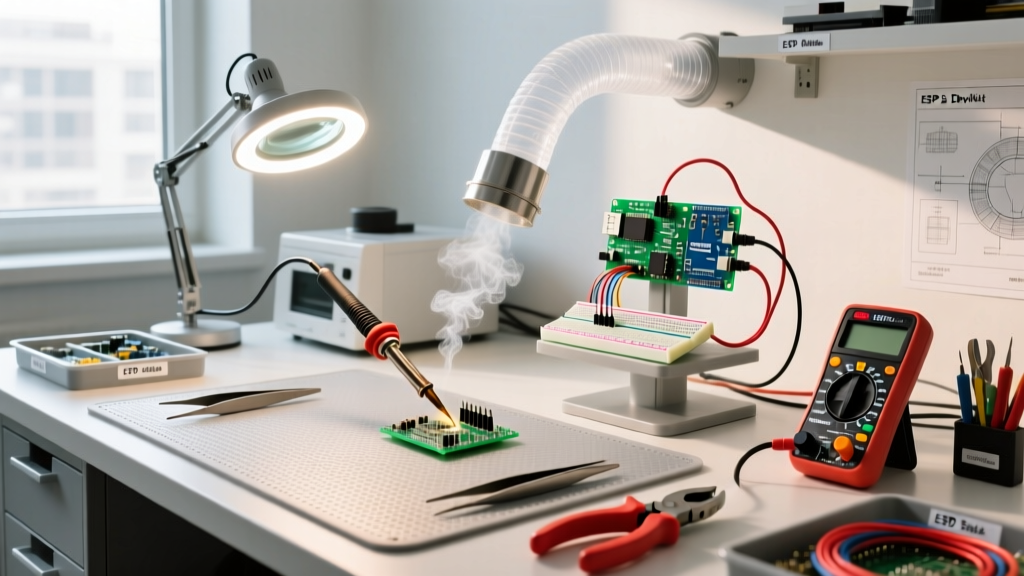
Soldering in electronics is not a monolithic skill; it is a dynamic interplay of thermal management, metallurgical chemistry, and fluid dynamics. Whether you are assembling a high-density IoT sensor board or repairing a vintage audio amplifier, applying a one-size-fits-all approach leads to cold joints, pad delamination, and latent field failures. According to the Association Connecting Electronics Industries (IPC), over 60% of printed circuit board (PCB) assembly defects are directly traceable to improper soldering profiles and material mismatches.
This decision framework is designed for engineers, technicians, and advanced hobbyists to systematically select the right materials and tools for their specific electronic applications. By treating soldering as a series of binary and conditional decisions, you can eliminate guesswork and optimize joint reliability.
Decision 1: Solder Alloy Selection Matrix
The first critical decision hinges on your regulatory environment and the thermal tolerance of your components. In 2026, the divide between commercial RoHS-compliant manufacturing and hobbyist prototyping remains distinct.
| Alloy Designation | Composition | Melting Point | Primary Use Case | Cost (Approx/lb) |
|---|---|---|---|---|
| Sn63/Pb37 | 63% Tin, 37% Lead | 183°C (Eutectic) | Hobbyist, aerospace, vintage repair | $35 - $45 |
| SAC305 | 96.5% Sn, 3% Ag, 0.5% Cu | 217°C - 220°C | Commercial RoHS, high-reliability | $40 - $55 |
| Sn62/Pb36/Ag2 | 62% Sn, 36% Pb, 2% Ag | 179°C | Silver-plated component leads | $60 - $75 |
| Bi58/Sn42 | 58% Bismuth, 42% Tin | 138°C | Low-temp SMD rework, heat-sensitive ICs | $45 - $60 |
The Eutectic Advantage
For general prototyping and through-hole work, Sn63/Pb37 remains the undisputed champion. Because it is eutectic, it transitions directly from solid to liquid at exactly 183°C without a plastic (semi-solid) phase. This eliminates the risk of 'disturbed joints'—a common failure mode where micro-vibrations during the cooling phase cause microscopic fractures in the crystalline structure. If you are doing commercial production, SAC305 is mandatory, but it requires higher iron temperatures (typically 350°C - 380°C) and more aggressive fluxes to achieve proper wetting.
Decision 2: Matching Thermal Delivery to Joint Mass
Selecting a soldering station is fundamentally a decision about thermal recovery and sensor placement. The market is currently split between traditional ceramic heater wands and active-tip cartridge systems.
Traditional Ceramic Stations (e.g., Hakko FX-888D)
Priced around $115, the Hakko FX-888D (65W) is the industry baseline. However, its thermocouple is located inside the ceramic wand, millimeters away from the actual tip surface. When you apply the tip to a heavy ground plane, the tip temperature drops, and the sensor takes 8 to 12 seconds to register the loss and ramp the heater. This delay often results in operators applying excessive dwell time, risking pad delamination on standard FR4 boards (which have a glass transition temperature, Tg, of roughly 130°C to 150°C).
Active-Tip Cartridge Systems (e.g., JBC CD-2BE)
For high-density mixed-technology boards, active-tip stations like the JBC CD-2BE ($525) or the budget-friendly Pinecil V2 ($26) are superior. In these systems, the heating element and thermocouple are integrated directly into the tip cartridge. The JBC C245 tips, for instance, recover from a 50°C temperature drop in under 2 seconds. This allows you to solder a 0402 SMD capacitor and a 10AWG power lug on the same board without adjusting the temperature dial.
Pro-Tip for Ground Planes: If you must solder a through-hole connector to a multi-layer board with internal copper pours, do not simply turn up the iron temperature to 400°C. This oxidizes the tip and burns the flux. Instead, use a station with high thermal mass (like a 130W JBC or a Metcal MX-5200) and a chisel tip with a wide contact area to maximize conductive heat transfer.
Decision 3: Flux Chemistry and Activation Thresholds
Flux is the chemical engine of soldering; it strips oxidation from the copper pad and the component lead, allowing the molten solder to form an intermetallic bond. Choosing the wrong flux chemistry for your cleaning capabilities is a primary cause of long-term electrochemical migration (dendritic growth).
- Rosin Mildly Activated (RMA): The standard for general electronics (e.g., Kester 186). Activates around 150°C. Leaves a hard, amber residue that is generally non-corrosive and can be left on the board or cleaned with isopropyl alcohol (IPA).
- No-Clean (NC): Formulated for high-volume SMD assembly (e.g., Amtech NC-559). The residue is designed to be left on the board. Warning: If you heat no-clean flux multiple times during rework, the protective encapsulation breaks down, and the residue can become mildly corrosive.
- Water-Soluble (Organic Acid): Highly active, excellent for stubborn oxidations (e.g., Kester 331). Critical Requirement: Must be cleaned with deionized (DI) water immediately after soldering. If left on the PCB, it will aggressively corrode traces and cause short circuits within weeks.
Decision 4: SMD vs. Through-Hole Execution Strategy
As the Adafruit Guide to Excellent Soldering notes, surface mount technology (SMT) requires a fundamentally different approach to heat application compared to through-hole technology (THT).
Through-Hole (THT) Execution
For THT, the decision is straightforward: use a bevel or chisel tip. The goal is to heat the barrel of the plated through-hole and the component lead simultaneously. Apply the iron for 1 second, feed 0.062-inch (1.5mm) diameter solder into the joint (not the iron tip), and remove the solder, then the iron. Total dwell time should not exceed 3 seconds.
Surface Mount (SMD) Execution
For SMD components (especially QFN or BGA packages), a standard iron is insufficient. You must decide between hot air reflow and solder paste stenciling.
- Hot Air Rework: Using a station like the Quick 861DW ($250), set the airflow to 40L/min and temperature to 360°C. Preheat the entire board to 100°C using an IR mat to prevent the 'tombstoning' effect, where one pad of a capacitor heats faster than the other, pulling the component upright.
- Reflow Paste: For prototyping multiple SMD boards, use a solder paste like Chip Quik SMD291AX (Sn63/Pb37) applied via a stainless steel stencil. Reflow using a modified toaster oven or a dedicated benchtop reflow oven (e.g., Miniware MHP30) following a strict thermal profile: preheat to 150°C for 90 seconds, ramp to 210°C for reflow, and cool naturally.
Diagnosing Edge Cases and Failure Modes
Even with the right framework, environmental and material variables can induce specific failure modes. The NASA Electronic Parts and Packaging (NEPP) program provides rigorous guidelines on identifying these microscopic defects.
1. The 'Icicle' or 'Rosin Spike' Joint
Symptom: A pointed, icicle-like protrusion extending from the solder joint. Root Cause: The iron was removed before the flux fully activated and boiled off, or the soldering temperature was too low for the thermal mass of the joint. Correction: Re-apply fresh RMA flux, increase iron temperature by 15°C, and apply heat for an additional 1.5 seconds to allow the flux to reduce surface tension and pull the solder into a smooth fillet.
2. Pad Delamination (Lifting)
Symptom: The copper pad peels away from the FR4 substrate. Root Cause: Dwell time exceeded 4-5 seconds, or iron temperature was set above 400°C, degrading the epoxy resin binding the copper to the fiberglass. Correction: Never attempt to solder a lifted pad back down with more heat. Use a high-strength cyanoacrylate or two-part epoxy to mechanically bond the pad back to the substrate, then reinforce the joint with a small gauge jumper wire.
3. Solder Balling and Splatter
Symptom: Microscopic spheres of solder scattered around the joint. Root Cause: Moisture trapped inside the solder wire's flux core expanding rapidly into steam upon contact with a 350°C tip. Correction: Store solder wire in a dry, climate-controlled environment. If using water-soluble paste, ensure the PCB has been baked at 100°C for 2 hours prior to assembly to drive out absorbed ambient humidity.
Summary Checklist for Your Workbench
Before initiating any electronic assembly run, verify the following parameters against your decision framework:
- Alloy Match: Does the solder alloy match the component finish and RoHS requirements?
- Thermal Capacity: Is the station's wattage and tip geometry sufficient for the largest ground plane on the board?
- Flux Compatibility: Do you have the correct cleaning solvent (IPA or DI water) on hand for the specific flux core being used?
- Tip Maintenance: Is the tip tinned with a sacrificial layer of solder to prevent oxidation during idle periods?
By treating soldering in electronics as a structured series of material and thermal decisions rather than a manual craft, you ensure repeatable, high-yield assemblies that meet modern reliability standards.