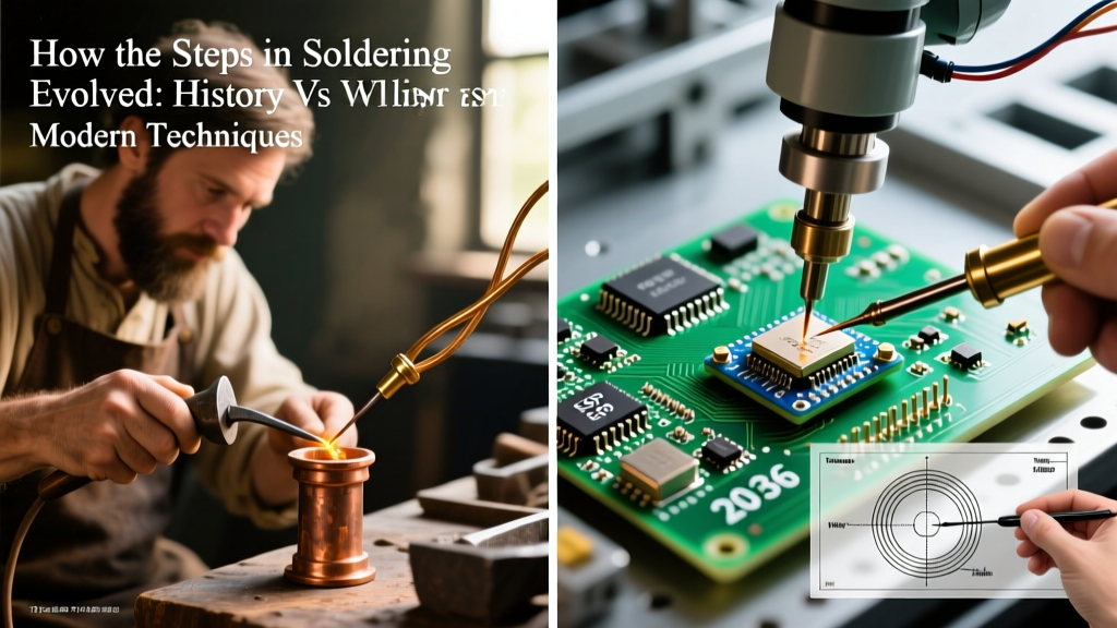

The Evolution of Soldering Assembly in Modern Electronics
Choosing the right soldering assembly method is one of the most critical decisions in printed circuit board (PCB) manufacturing. Whether you are scaling from a garage prototype to a 10,000-unit production run, the transition between manual and automated assembly dictates your yield rate, capital expenditure, and compliance with IPC standards. In 2026, the shift toward low-temperature lead-free alloys and high-density interconnect (HDI) boards has forced engineers to re-evaluate traditional assembly lines. This guide provides a deep-dive technical comparison of the four primary soldering assembly methods: Hand, Wave, Reflow, and Selective.
Core Soldering Assembly Methods: Comparison Matrix
Before dissecting the metallurgical and thermal nuances of each process, it is essential to understand the macro-level trade-offs. The table below outlines the baseline metrics for low-to-medium volume buyers.
| Assembly Method | Primary Application | Estimated Equipment Cost | Throughput | Common Defect Modes |
|---|---|---|---|---|
| Hand Soldering | Prototyping, Rework, Low-Volume THT | $150 - $500 per station | Low (Operator dependent) | Cold joints, pad lift, flux entrapment |
| Wave Soldering | High-Volume Through-Hole (THT) | $80,000 - $150,000+ | High (Boards per minute) | Bridging, icicles, copper leaching |
| Reflow Soldering | High-Volume Surface Mount (SMT) | $60,000 - $120,000+ | Very High (Continuous belt) | Tombstoning, voiding, head-in-pillow |
| Selective Soldering | Mixed-Technology (SMT + THT) | $100,000 - $200,000+ | Medium (Programmable) | Shadowing, insufficient wetting |
Deep Dive: Hand Soldering Assembly vs. Automated Methods
Hand Soldering Assembly: The Prototyper’s Staple
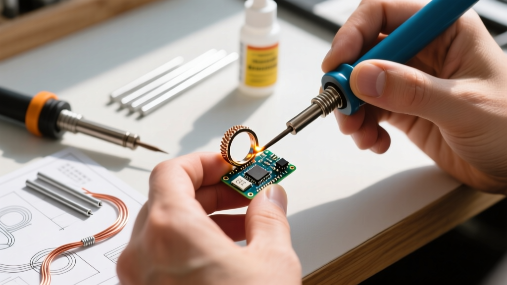
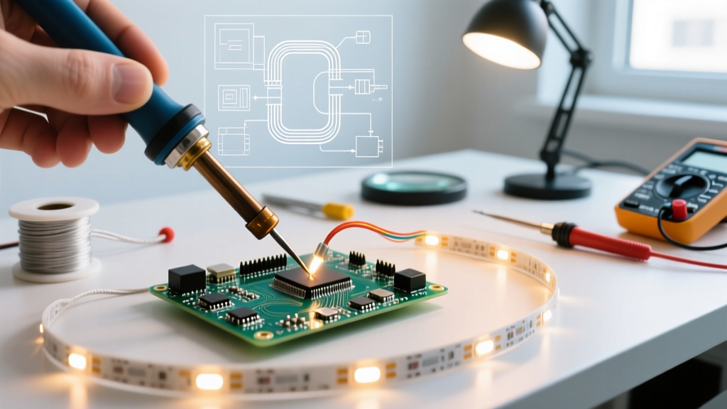
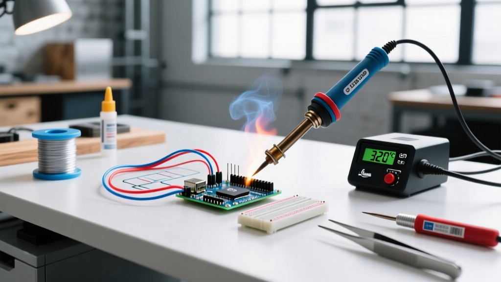
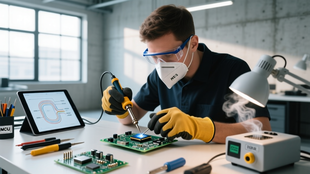
Despite the dominance of automation, hand soldering assembly remains indispensable for low-volume runs, complex rework, and aerospace applications where NASA workmanship standards demand human verification of every joint. Modern hand soldering relies heavily on active-tip technology to manage the thermal demands of lead-free alloys.
- Equipment Specifics: Industry staples like the Hakko FX-951 or Weller WE1010NA utilize high-wattage (70W-100W) heaters embedded directly in the tip. This ensures rapid thermal recovery when soldering to large ground planes.
- Alloy & Thermal Management: The standard SAC305 (Sn96.5/Ag3.0/Cu0.5) alloy requires tip temperatures of 350°C to 380°C. However, prolonged dwell times at these temperatures risk delaminating the PCB substrate. Operators must adhere to a strict maximum dwell time of 3 seconds per joint to prevent pad lift and barrel cracking in plated through-holes (PTH).
- Failure Modes: The most prevalent defect in manual assembly is the "cold joint," characterized by a dull, grainy appearance and poor metallurgical wetting. This occurs when the iron heats the lead but fails to adequately raise the temperature of the PCB pad above the alloy's liquidus point (217°C for SAC305).
Wave Soldering Assembly: The THT Workhorse
When a design relies heavily on through-hole components—such as large electrolytic capacitors, heavy transformers, or edge connectors—wave soldering assembly is the undisputed champion of throughput. The board passes over a standing wave of molten solder, creating thousands of joints in seconds.
- Fluxing: Boards are first coated with a VOC-free, water-based flux via ultrasonic nozzles. This removes oxides and lowers surface tension.
- Preheating: Infrared or forced-convection preheat zones raise the board temperature to 100°C–120°C. This is critical to activate the flux and prevent thermal shock when the board hits the 265°C solder wave.
- The Wave Contact: Boards typically pass over a turbulent "chip wave" (to penetrate tight spaces under SMT components glued to the bottom) followed by a smooth "lambda wave" for final wetting and drainage.
Expert Insight: In 2026, many high-reliability manufacturers have transitioned from SAC alloys to SN100C (Sn99.3/Cu0.7/Ni) for wave soldering. The addition of nickel drastically reduces copper leaching from the PCB pads and PTH barrels, extending the lifespan of the solder bath and reducing dross generation by up to 15%.
Reflow Soldering Assembly: The SMT Standard
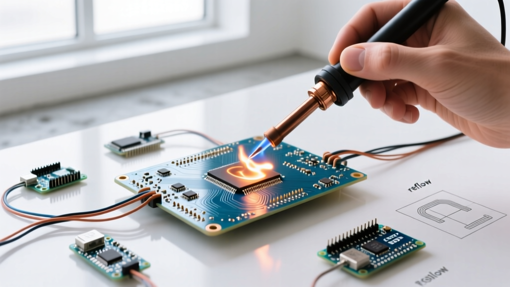
For modern, high-density designs utilizing 0201 passives, BGAs, and QFNs, reflow soldering assembly is mandatory. This process involves printing solder paste through a stencil, placing components via pick-and-place machines, and passing the assembly through a multi-zone convection reflow oven.
The success of reflow hinges entirely on the thermal profile. Engineers must program the oven's conveyor speed and zone temperatures to achieve a specific curve:
- Ramp: Gradual heating (1°C to 3°C per second) to prevent solder paste spattering and solder ball defects.
- Soak: Holding the board at 150°C–180°C for 60–90 seconds. This allows the flux to volatilize and equalizes the temperature across components of varying thermal masses.
- Reflow (Spike): Pushing the peak temperature to 240°C–250°C. The Time Above Liquidus (TAL) must be strictly maintained between 45 and 60 seconds. Exceeding 90 seconds can cause excessive intermetallic compound (IMC) growth, resulting in brittle joints.
Advanced Failure Modes: "Tombstoning" occurs when uneven wetting forces pull a small passive component upright. This is often caused by asymmetric pad design or uneven heating in the soak zone. Another critical defect is "Head-in-Pillow" (HiP), common in BGA assembly, where the solder paste and the component's pre-tinned ball melt but fail to coalesce due to oxidation or insufficient flux activity.
Selective Soldering: Bridging the Mixed-Technology Gap
As the industry moves away from wave soldering due to environmental concerns and the need for selective fluxing, selective soldering assembly has emerged as the premier solution for mixed-technology boards. Machines like the ERSA VERSAFLOW utilize a miniature, programmable solder nozzle that moves beneath the board via CNC axes, soldering only specific THT pins while avoiding sensitive SMT components.
While the capital expenditure is high (often exceeding $150,000), selective soldering eliminates the need for expensive custom pallets and masks required in wave soldering. It also allows for precise, localized thermal profiling, making it ideal for IPC Class 3 aerospace and medical assemblies where zero-defect mandates apply.
Decision Framework: Choosing Your Assembly Line
Selecting the optimal soldering assembly method requires balancing volume, component mix, and budget. Use this framework to guide your capital equipment purchases:
- 1 to 500 Units (Prototyping & NPI): Rely on Hand Soldering Assembly for THT and small-batch SMT rework. Invest in a high-end active-tip station ($300) and a basic hot-air rework station ($200) for QFN/BGA reflow.
- 500 to 5,000 Units (Mid-Volume): Utilize a contract manufacturer (CM) with Reflow Soldering Assembly lines. If bringing in-house, consider benchtop reflow ovens (e.g., LPKF ProtoFlow) costing around $5,000–$10,000, paired with manual stencil printing.
- 10,000+ Units (High-Volume Mass Production): Full Reflow Soldering for SMT is non-negotiable. For heavy THT integration, transition from traditional wave to Selective Soldering Assembly to reduce dross waste, eliminate masking labor, and comply with modern SMTA sustainability guidelines.
Quality Standards and Final Verification
Regardless of the method chosen, all soldering assembly must be verified against the IPC-A-610 Acceptability of Electronic Assemblies standard. For commercial products (Class 2), joints must exhibit smooth, continuous wetting with a contact angle of less than 90 degrees. For high-reliability sectors (Class 3), the requirements tighten significantly, demanding specific solder fillet heights and zero tolerance for exposed copper in the joint vicinity.
Ultimately, the best soldering assembly method is the one that aligns with your design's thermal mass, component density, and production volume. By understanding the metallurgical limits of your chosen alloys and the thermal mechanics of your equipment, you can drastically reduce scrap rates and ensure long-term field reliability.