
Beyond the Soldering Iron: Navigating Material Compatibility
While traditional tin-lead or SAC305 (lead-free) soldering remains the backbone of electronics assembly, it is fundamentally a thermal process limited by metallurgical compatibility and heat tolerance. When working with heat-sensitive substrates like polyimide flex circuits, dissimilar metals prone to galvanic corrosion, or high-vibration environments where intermetallic compounds (IMCs) fatigue and crack, standard soldering fails. As manufacturing and DIY prototyping evolve in 2026, selecting the right soldering alternatives is no longer just about avoiding heat—it is about optimizing mechanical strength, electrical conductivity, and long-term reliability.
This guide provides a deep-dive material compatibility matrix for the most effective soldering alternatives, including conductive epoxies, precision crimping, wire wrapping, and ultrasonic welding. We will examine specific product models, exact failure modes, and tooling costs to help you engineer the right joint for your specific substrate.
1. Conductive Epoxies for Heat-Sensitive & Flexible Substrates
Conductive adhesives (ICAs) replace the thermal bonding of solder with a chemical cure, utilizing a polymer matrix (usually epoxy or silicone) loaded with conductive particles like silver, copper, or carbon. They are the premier choice for attaching components to flexible PCBs (FPCs), glass substrates, or heat-sensitive RF modules.
Product Spotlight: Silver-Filled vs. Carbon-Filled
For high-reliability electrical connections, silver-filled epoxies are the industry standard. A leading formulation is the MG Chemicals 8331 Silver Conductive Epoxy. It offers a volume resistivity of roughly 0.0006 ohm-cm, which, while higher than bulk copper, is more than sufficient for signal traces and low-power sensor attachments.
- Curing Profile: 5 minutes at 100°C, or 24 hours at room temperature (25°C).
- Shear Strength: Typically exceeds 15 MPa when fully cured, providing excellent mechanical hold without the brittle IMC layer found in solder joints.
- Failure Mode: The primary failure mode for conductive epoxies is CTE (Coefficient of Thermal Expansion) mismatch. If subjected to extreme thermal cycling (e.g., -40°C to +125°C automotive environments), the polymer matrix expands and contracts at a different rate than the silicon die or copper pad, leading to micro-cracking and a spike in contact resistance.
For applications requiring extreme flexibility, such as wearable electronics, silicone-based conductive adhesives like Henkel Loctite Ablestik 2902 are preferred. They sacrifice some volumetric conductivity for an elongation-at-break rating exceeding 100%, allowing the joint to bend without fracturing. For deeper technical specifications on adhesive formulations, refer to the MG Chemicals conductive adhesives catalog.
2. Mechanical Crimping for High-Vibration & Dissimilar Metals
When joining copper to aluminum, or when routing wires in high-vibration environments (aerospace, automotive, industrial robotics), soldering is actively detrimental. Solder wicks into the wire strands via capillary action, creating a rigid transition point just outside the solder joint that acts as a stress concentrator, leading to strand fatigue and breakage. Cold-weld crimping avoids this entirely.
The Anatomy of a Mil-Spec Crimp
A proper crimp creates a cold weld between the wire strands and the terminal barrel, achieving up to 90% of the wire's tensile strength. For professional and advanced DIY applications, TE Connectivity PIDG (Pre-Insulated Diamond Grip) terminals are the benchmark. The copper sleeve inside the insulation barrel provides secondary strain relief, crucial for dynamic wiring.
Expert Tip: Never use solder on a crimped terminal. According to IPC wiring and crimping standards, adding solder to a crimp joint makes it brittle and prone to vibration-induced failure. The crimp must remain a cold-welded, gas-tight mechanical deformation.
Tooling and Die Selection
Achieving a gas-tight crimp requires precise compression. Ratcheting crimpers, such as the Knipex 97 53 14 (for insulated terminals) or the Molex 63819-0000 hand crimper (for open-barrel micro-fit terminals), ensure the tool only releases once the exact deformation depth is reached. For 22-18 AWG wire, the die must compress the barrel to a specific hexagonal or quad-point profile, ensuring the wire strands deform into the terminal walls without cutting the copper.
Galvanic Corrosion Warning: If you must transition between copper wire and an aluminum busbar, use a bimetallic lug or apply an antioxidant joint compound (like Noalox) before crimping to prevent galvanic degradation, which will rapidly increase resistance in humid environments.
3. Ultrasonic and Resistance Welding for Battery Interconnects
The explosion of custom Li-ion battery packs (using 18650, 21700, and the newer 4680 cells) has made spot welding a critical soldering alternative. Soldering directly to a lithium cell terminal is highly discouraged; the heat required to melt SAC305 solder can damage the cell's internal CID (Current Interrupt Device) or degrade the electrolyte.
Resistance Spot Welding Parameters
For DIY and low-volume production, resistance spot welders pass a high-current, low-voltage pulse through copper electrodes to fuse a nickel strip to the steel or aluminum cell cap.
- Material: 99.9% pure nickel strips (0.15mm thickness for 18650s; 0.20mm to 0.30mm for high-current 21700s). Never use nickel-plated steel, as its higher resistance causes excessive surface arcing and weak welds.
- Pulse Timing: A typical dual-pulse weld on a 21700 cell uses a 5ms 'pre-weld' pulse to seat the strip, followed by a 15ms 'main weld' pulse at roughly 1500-2000 Amps.
- Failure Mode: 'Explosions' or severe sparking occur if the electrode force is too low, creating high contact resistance that vaporizes the metal rather than forging it. Proper pneumatic or heavy-spring electrode pressure (approx. 4-6 kg of force) is mandatory.
Material Compatibility & Failure Mode Matrix
Selecting the correct soldering alternative requires matching the substrate metallurgy and environmental stressors to the joining method. Use the matrix below to diagnose the optimal approach for your project.
| Substrate / Material | Recommended Alternative | Key Advantage | Primary Failure Mode to Avoid |
|---|---|---|---|
| Polyimide Flex PCB (FPC) | Silver Conductive Epoxy | No thermal warping; maintains flexibility. | CTE mismatch cracking under thermal shock. |
| Copper to Aluminum | Bimetallic Crimp Lugs | Prevents galvanic corrosion; gas-tight seal. | Oxidation buildup if antioxidant paste is omitted. |
| Li-Ion Cell Terminals | Resistance Spot Welding | Zero heat transfer to internal cell chemistry. | Surface arcing due to insufficient electrode pressure. |
| High-Vibration AWG Wire | Cold-Weld Ratchet Crimp | Strands remain flexible; no stress concentrators. | Strand cutting from improper die compression. |
| RF Shielding / Grounding | Conductive Copper Tape | Instant adhesion; conforms to complex 3D shapes. | Adhesive drying out and peeling in high-heat zones. |
Tooling Cost & ROI Analysis for 2026
Transitioning from a $50 soldering station to alternative joining methods requires an upfront tooling investment. However, the ROI is realized in reduced scrap rates and expanded manufacturing capabilities.
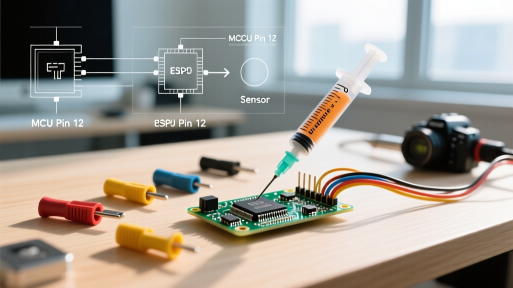
- Conductive Epoxy Route: Lowest barrier to entry. A 50g syringe of MG Chemicals 8331 costs approximately $65. A precision dispensing syringe and blunt-tip needles add $15. Total: ~$80. Ideal for PCB repair and flexible circuits.
- Precision Crimping Route: A high-quality ratcheting crimper (e.g., IWISS SN-28B or Molex equivalents) ranges from $45 to $150. However, building a comprehensive die set for micro-fit, JST, and standard PIDG terminals can easily push the total investment past $400. Essential for robotics and automotive wiring.
- Spot Welding Route: Entry-level DIY spot welders (like the Malectrics or Kweld clones) start around $150, but a reliable, digitally controlled pulse welder (such as the Sunkko 738G) costs between $350 and $500. Add $40 for a roll of 0.15mm pure nickel strip. Mandatory for battery pack assembly.
For professional shops, exploring advanced terminal and splice solutions via suppliers like TE Connectivity can streamline high-volume crimping processes, justifying the cost of automated or semi-automated pneumatic crimp presses.
Final Verdict: Engineering the Right Joint
The pursuit of soldering alternatives is rarely about completely abandoning the soldering iron; rather, it is about recognizing the physical and chemical limits of molten metal alloys. When your substrate melts before the solder flows, conductive epoxies bridge the gap. When vibration shatters brittle IMC layers, cold-weld crimping provides mechanical supremacy. And when dealing with volatile energy storage, resistance welding ensures safety and conductivity. By understanding the material compatibility and specific failure modes of each alternative, you can design assemblies that survive the rigors of real-world deployment long after the flux has faded.