
The Hidden Dangers of Soldering Ring Terminals Together
In the electrical and electronics DIY community, the phrase 'soldering rings together' almost exclusively refers to the practice of soldering ring terminals (lugs) to stranded wire and then stacking or bolting those rings together on a common grounding stud or power distribution block. While soldering provides a solid electrical connection in low-stress, low-current PCB environments, applying this technique to mechanical ring terminal connections introduces severe safety hazards. As of 2026, with the rapid expansion of high-amperage DC systems in residential solar arrays, off-grid battery banks, and EV charging stations, understanding the alternatives to soldering rings together is no longer optional—it is a critical safety requirement.
When you solder a ring terminal to a wire and then compress it under a bolt, you create a mechanical joint relying on a soft metal alloy. Solder (whether traditional Sn63/Pb37 or lead-free SAC305) is highly susceptible to thermal creep and cold flow. Under the continuous compressive torque of a bolted joint, the solder slowly deforms. Over months of thermal cycling, the joint loosens, increasing electrical resistance. This elevated resistance generates localized heat (I²R losses), which further accelerates the creep in a runaway thermal feedback loop, ultimately leading to arcing, melted insulation, and electrical fires.
What the Standards Say
According to the NASA-STD-8739.4 workmanship manual for crimping, soldering, and wire harness assemblies, solder should never be used as the sole mechanical retention method for heavy-gauge wire terminations subject to vibration or high mechanical stress. Similarly, the National Electrical Code (NFPA 70 / NEC) strictly mandates that terminations must be made using listed connectors (like crimped lugs) that are torqued to manufacturer specifications, effectively ruling out soft-soldered ring joints for branch circuit wiring.
Comparison Matrix: Ring Terminal Termination Methods
To help you choose the right approach for your next wiring project, we have evaluated the primary alternatives to soldering rings together based on safety, cost, and reliability in 2026.
| Method | Upfront Tool Cost | Vibration Resistance | Thermal Creep Risk | Best Application |
|---|---|---|---|---|
| Soldering (Sn63/SAC305) | $30 - $80 | Poor | High (Severe) | Low-stress PCB jumpers only |
| Ratcheting Crimp + Heat Shrink | $45 - $120 | Excellent | None | DC wiring, automotive, marine |
| Hydraulic Crimping | $150 - $400 | Excellent | None | Heavy gauge (2/0 to 4/0 AWG) |
| Mechanical Busbars / Lugs | $20 - $150 | Good | Low (if torqued) | Power distribution, battery banks |
| Exothermic Welding (Cadweld) | $100+ per joint | Superior | None | Residential grounding rings/rods |
Alternative 1: Ratcheting Crimp Connectors (The Industry Standard)
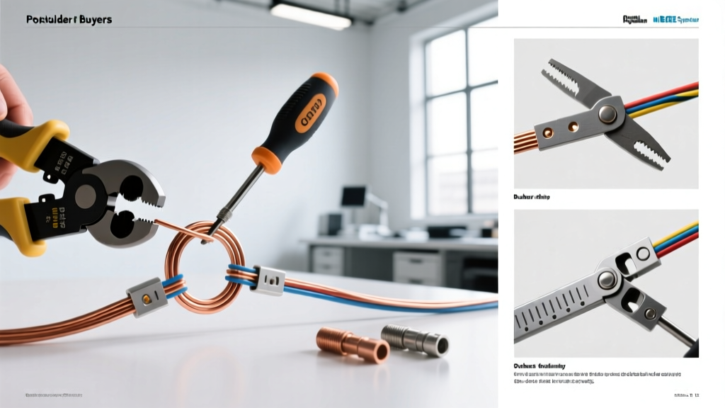
The most direct and reliable alternative to soldering rings together in standard gauge wiring (16 AWG to 2 AWG) is the ratcheting crimp. Unlike soldering, which merely glues the wire to the lug, a proper crimp creates a cold weld—a gas-tight, metallurgical bond between the copper wire strands and the terminal barrel. This bond is immune to thermal creep and highly resistant to vibration.
Tooling and Material Specifics
- The Crimper: Avoid cheap, non-ratcheting pliers. Invest in a dedicated ratcheting crimper like the IWISS IWS-16 (typically $45–$55 in 2026) or the Wirefy Heavy Duty Crimper. These tools feature a ratcheting mechanism that prevents the jaws from opening until the exact required compression force is achieved, ensuring you never under-crimp a connection.
- The Terminals: Use tinned copper ring terminals with an adhesive-lined polyolefin heat shrink collar. Brands like 3M MDT or Wirefy offer dual-wall heat shrink that melts its inner adhesive layer when heated, creating a waterproof seal that prevents capillary action from drawing moisture into the wire strands.
- Wire Prep: Strip the wire precisely. For a 10 AWG wire in a #10 stud ring terminal, the strip length is typically 5/16". The wire should be flush with the end of the metal barrel before crimping. Never tin the wire with solder before crimping; this defeats the cold-weld mechanism and introduces the exact creep risks you are trying to avoid.
Alternative 2: Mechanical Busbars and Terminal Blocks
A common scenario where DIYers attempt 'soldering rings together' is when they need to connect multiple ground wires or power feeds to a single point. Stacking five soldered ring terminals on a single 1/4" bolt creates uneven compression. The middle rings often lose contact pressure as the outer rings deform, leading to localized hotspots.
The safe alternative is to use an engineered Power Distribution Busbar. For marine, automotive, and solar applications, the Blue Sea Systems 2506 (rated for 250A continuous) features tin-plated copper buses with dedicated, isolated studs. Instead of stacking rings, you route each crimped ring terminal to its own dedicated stud, ensuring uniform torque and equal current distribution. For smaller AC/DC transitions, lever-nut terminal blocks like the WAGO 221 series eliminate the need for ring terminals entirely, allowing you to safely bond multiple stripped wires in a UL-listed, vibration-proof housing.
Alternative 3: Exothermic Welding for Grounding Rings
When dealing with heavy-gauge grounding rings (such as 2/0 AWG or 4/0 AWG bare copper connecting to a grounding rod or structural steel), neither soldering nor standard crimping is sufficient for long-term burial or high-fault-current scenarios. The ultimate alternative is Exothermic Welding (often referred to by the brand name nVent ERICO Cadweld).
This process uses a chemical reaction between copper oxide and aluminum powder to generate superheated molten copper (around 2,500°F / 1,370°C). The molten copper is poured into a graphite mold encasing the grounding ring and the rod. The result is a solid, molecular bond that possesses higher tensile strength than the original wire and zero electrical resistance. While the upfront cost per joint is high (molds and cartridges cost $30-$50 each), it is the only method universally accepted by the NEC and IEEE for permanent, maintenance-free grounding ring connections.
Step-by-Step: Transitioning from Solder to Crimp for Ring Lugs
If you are retrofitting an existing DIY battery bank or solar combiner box where rings were previously soldered together, follow this safety protocol:
- De-energize and Verify: Disconnect all power sources and use a CAT III or CAT IV multimeter to verify zero voltage across the busbars.
- Remove and Inspect: Unbolt the soldered ring terminals. Inspect the wire insulation. If the soldering process caused the PVC or silicone insulation to become brittle, discolored, or melted, you must cut the wire back to clean, undamaged copper.
- Strip and Clean: Strip the wire to the exact depth of the new crimp barrel. Use a dedicated wire brush or Scotch-Brite pad to lightly clean the copper strands, removing any residual oxidation or old solder flux.
- Crimp: Insert the wire into the bare metal barrel of the adhesive-lined ring terminal. Place the assembly into the correct die of your ratcheting crimper and squeeze until the ratchet releases.
- Seal: Apply heat evenly around the shrink collar using a precision hot air gun (set to roughly 250°C / 480°F). Stop heating the moment the adhesive begins to slightly ooze from the edges, indicating a complete environmental seal.
- Torque: Bolt the new crimped rings to the busbar. Use a calibrated inch-pound torque wrench. For example, a standard #10-32 brass nut on a copper busbar typically requires 2.5 Nm (22 in-lbs) of torque. Always consult the hardware manufacturer's torque chart.
Edge Cases: High-Vibration and Galvanic Corrosion Risks
Even when utilizing crimped alternatives to soldering rings together, environmental factors can compromise safety if ignored. In high-vibration environments (such as under the hood of a vehicle or near heavy inverters with cooling fans), standard ring terminals can suffer from mechanical fatigue at the junction where the barrel meets the ring stud hole. Always use flanged or butted-seam ring terminals in these scenarios, as they offer superior structural integrity compared to brazed-seam terminals.
Furthermore, if you are bolting copper ring terminals to an aluminum busbar or chassis, you must address galvanic corrosion. Copper and aluminum in the presence of atmospheric moisture create a galvanic cell that rapidly oxidizes the aluminum, increasing resistance. Always apply a conductive antioxidant compound (such as Noalox or Penetrox E) to the joint interface before torquing the bolt. This compound displaces moisture and contains zinc dust that sacrificially corrodes instead of your primary conductors.
Frequently Asked Questions
Can I solder a wire, put a ring terminal over it, and then crimp?
No. The IPC-A-620 standard explicitly warns against this. Soldering the wire before crimping makes the wire bundle rigid. When the crimper applies force, the rigid soldered bundle can crack, and the terminal barrel will crimp onto the hard solder rather than deforming into the individual copper strands. This results in a weak mechanical joint prone to pulling out under tension.
Is it ever safe to stack multiple ring terminals on one bolt?
While it is common practice to stack up to two or three properly crimped, flat ring terminals on a single stud (provided they are of identical width and the bolt is long enough to maintain full thread engagement), stacking more than three is highly discouraged. Beyond three rings, the cumulative tolerance stack-up and uneven compression drastically increase the risk of the inner rings losing torque. Use a multi-stud busbar instead.
What is the best alternative for small electronics (under 22 AWG)?
For micro-electronics where ring terminals are too large, the safest alternative to soldering wires directly to a common ground ring is to use a Zero-Ohm resistor or a dedicated grounding jumper wire on the PCB, or utilize a micro-terminal block (like the JST PH series) to bring the connections to a centralized, mechanically stable point.