
The Foundation: Selecting the Right Soldering Station
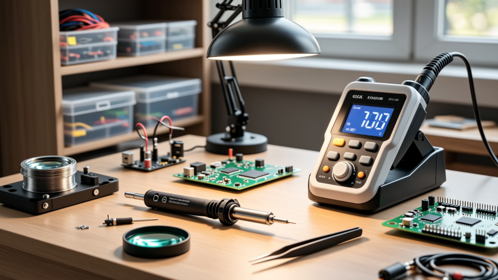
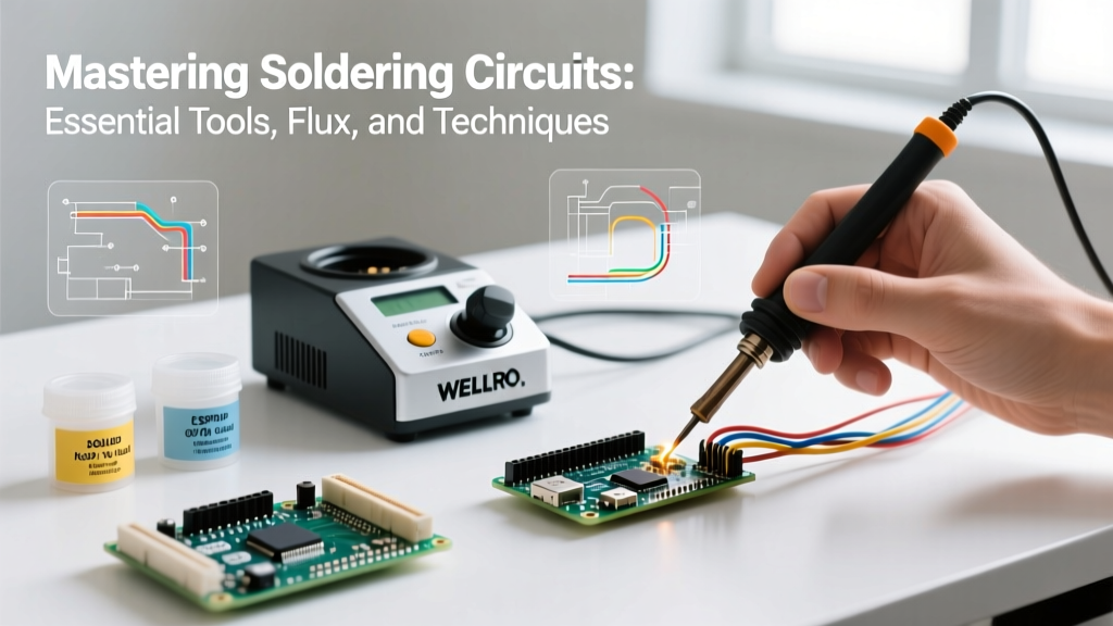
When evaluating professional equipment for soldering circuits, thermal recovery is paramount. A station might boast 70 watts on paper, but if the sensor loop is slow, the tip temperature will plummet when touching a multi-layer ground plane, resulting in cold joints and pad delamination. According to Hakko's technical guidelines, ceramic heating elements with integrated tip sensors provide the fastest thermal recovery, which is critical for modern high-density PCBs.
| Model | Wattage | Temp Range | Price (2026) | Best For |
|---|---|---|---|---|
| Hakko FX-888D | 70W | 120-480°C | $110 | General Through-Hole & SMD |
| Weller WE1010 | 70W | 100-450°C | $115 | Precision Micro-SMD |
| Pinecil V2 | 65W (PD) | 100-450°C | $26 | Portable / Field Rework |
| Quick 861DW | 1000W | 100-500°C | $285 | Hot Air BGA / SMD Rework |
Solder Alloy Metallurgy: Leaded vs. Lead-Free
The choice of solder alloy dictates your working temperature, wetting characteristics, and joint reliability. For hobbyists and prototyping, 63/37 Tin/Lead (Sn63/Pb37) remains the gold standard. It is a eutectic alloy, meaning it transitions directly from solid to liquid at a single temperature (183°C / 361°F) without a plastic phase. This eliminates the risk of disturbing the joint during cooling, which can cause micro-fractures.
For commercial production or RoHS-compliant projects, SAC305 (Sn96.5/Ag3.0/Cu0.5) is the industry standard lead-free alloy. SAC305 has a higher melting point (217°C / 423°F) and requires a soldering iron temperature of roughly 350°C (662°F), compared to 315°C (600°F) for 63/37. Lead-free alloys also exhibit poorer wetting, making high-quality flux absolutely mandatory.
Expert Note: Never mix leaded and lead-free alloys on the same joint. The introduction of lead into a SAC305 joint creates a bismuth-lead eutectic phase that drastically lowers the melting point and creates severe mechanical brittleness, leading to catastrophic field failures.
Wire Gauge Selection
- 0.015" (0.4mm): Essential for 0402 and 0603 SMD components, and fine-pitch IC pins.
- 0.020" (0.5mm): The versatile middle-ground for 0805 SMD and standard through-hole resistors.
- 0.031" (0.8mm): Best for large through-hole components, power connectors, and heavy ground planes.
Flux Chemistry: The Unsung Hero of Circuit Soldering
Flux is a chemical cleaning agent that removes oxidation from the copper pads and component leads, allowing the molten solder to form a proper intermetallic bond. When soldering circuits, relying solely on the rosin core inside your solder wire is rarely enough for rework or SMD work.
Flux Types and Applications
- Rosin Mildly Activated (RMA): The standard for general through-hole work. It leaves a sticky residue that should be cleaned with isopropyl alcohol (IPA) to prevent long-term dendrite growth.
- No-Clean (NC): Formulated to leave a minimal, non-conductive, and non-corrosive residue. Products like Amtech NC-559-V2-TF or MG Chemicals 8341 are ideal for SMD and BGA rework where cleaning under tight clearances is impossible.
- Water-Soluble (OA): Highly active organic acid fluxes used for heavily oxidized boards. Must be thoroughly washed with distilled water immediately after soldering, or it will aggressively corrode the copper traces.
Tip Geometry and Maintenance
Choosing the correct tip geometry transfers heat efficiently without damaging adjacent components.
- Chisel (e.g., Hakko T18-D12): The 1.2mm chisel is the most versatile tip. The flat edge maximizes surface area contact for rapid heat transfer to through-hole leads and SMD pads.
- Conical (e.g., Weller RT1): Best for dragging solder across fine-pitch ICs (0.5mm pitch) and reaching into dense clusters of 0402 components.
- Bevel / Hoof: Excellent for drag-soldering SOIC and QFP packages, as the concave shape holds a small reservoir of molten solder.
Maintenance Rule: Never use a damp sponge to clean your tip; the thermal shock causes micro-cracking in the iron plating. Instead, use a dry brass wire sponge (like the Hakko 599B) and always leave a thick layer of solder on the tip before powering down to prevent oxidation.
Step-by-Step Workflow for Reliable Joints
According to SparkFun's soldering tutorials and IPC workmanship standards, a proper solder joint requires a specific sequence to ensure the intermetallic layer forms correctly without exceeding the FR-4 glass transition temperature (Tg).
- Prep: Apply a small amount of liquid or tack flux to the pads.
- Heat the Pad and Lead: Place the iron tip so it touches both the PCB pad and the component lead simultaneously. Hold for 1 to 1.5 seconds.
- Feed the Solder: Introduce the solder wire to the pad, not the iron tip. The flux will boil and the solder will wick into the joint via capillary action.
- Dwell Time: Remove the solder wire, then remove the iron. Total dwell time should not exceed 3 seconds to prevent pad lift.
- Cooling: Allow the joint to cool naturally. Do not blow on it, as this can cause a disturbed joint with a frosty, grainy appearance.
Troubleshooting Common Soldering Circuit Defects
When inspecting your work against the IPC-A-610 Acceptability of Electronic Assemblies standard, look out for these common failure modes:
Cold Joints
Symptoms: Dull, grainy, or lumpy appearance. The solder has not properly wetted the pad.
Cause: Insufficient heat, removing the iron too early, or moving the component while the solder was in the plastic phase.
Fix: Apply fresh flux, reheat the joint with a clean, tinned tip until the solder flows smoothly, and let it cool undisturbed.
Solder Bridges (Shorts)
Symptoms: Solder connects two or more adjacent pads, commonly seen on 0.5mm pitch TQFP or SOIC ICs.
Cause: Using too much solder, insufficient flux, or an oversized iron tip.
Fix: Apply a generous amount of No-Clean tack flux. Use a clean chisel tip or solder wick (desoldering braid) to gently drag the excess solder away from the pins.
Tombstoning
Symptoms: An SMD component (usually a capacitor or resistor) stands up on one end.
Cause: Uneven heating of the two pads, causing the surface tension of the molten solder on one side to pull the component upright.
Fix: Ensure your iron tip bridges both pads equally during heating, or use a hot air rework station to heat the entire component footprint uniformly.
Frequently Asked Questions (FAQ)
Can I use plumbing solder for electronic circuits?
No. Plumbing solder typically contains acid-core flux designed to eat through copper pipe oxidation. This acid will rapidly corrode PCB traces and component leads, leading to open circuits. Furthermore, plumbing solder is often a 50/50 Sn/Pb alloy with a wide plastic phase, making it unsuitable for delicate electronics. Always use rosin-core or no-clean electronic solder.
What is the best temperature for soldering circuits?
For 63/37 leaded solder, set your station to 315°C (600°F). For SAC305 lead-free solder, set it to 350°C (662°F). If you are soldering to a massive ground plane that acts as a heatsink, you may need to increase the temperature by 20°C or use a pre-heater mat set to 100°C to assist the top-side iron.
How do I clean flux residue off my PCB?
For RMA (Rosin Mildly Activated) flux, use 99% isopropyl alcohol (IPA) and a soft-bristle brush or lint-free swab. Avoid 70% rubbing alcohol, as the water content can trap moisture under components. For No-Clean flux, cleaning is generally unnecessary unless the board will be conformal coated or operated in high-humidity environments, in which case a specialized saponifier or high-purity solvent is required.