
The Metallurgical Reality: Why We Solder
In the realm of electronics and electrical wiring, the debate between mechanical fastening and soldering is ongoing. However, when executed to IPC-A-610 standards, soldered connections provide a continuous metallurgical bond that mechanical alternatives simply cannot match. The solder alloy does not merely "glue" the wires together; it forms an intermetallic compound (IMC) layer—typically Cu6Sn5 when using copper conductors—that ensures ultra-low electrical resistance and high mechanical tensile strength.
But this superior performance comes with inherent risks. A poorly executed solder joint doesn't just fail functionally; it becomes a severe safety hazard. High-resistance joints generate localized heat (I²R losses), potentially igniting nearby insulation. Furthermore, the process of creating these bonds exposes the operator to thermal hazards and toxic flux fumes. This guide outlines the critical safety best practices required to ensure your soldering workflow protects both the end-user and the technician.
Thermal Safety: Managing the 380°C Danger Zone
Modern lead-free soldering requires significantly higher thermal energy than legacy tin-lead (Sn63/Pb37) processes. While leaded solder flows smoothly at 350°C, lead-free alloys like SAC305 (e.g., Kester 24-6337-97026) require tip temperatures between 370°C and 380°C to achieve proper wetting.
Choosing the Right Station for Thermal Control
Using an underpowered iron forces technicians to dwell on the joint, transferring excessive heat into the wire insulation or PCB pads, which can cause delamination or melt wire jackets, exposing live conductors.
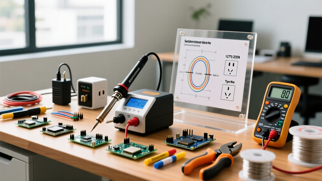
- Hakko FX-888D ($110): A reliable 70W entry-level station. Adequate for through-hole and light gauge wire (up to 14 AWG), but struggles with heavy ground planes, leading to dangerous prolonged dwell times.
- Weller WE1010NA ($115): Offers slightly faster thermal recovery due to its optimized heating element, reducing the temptation to crank the temperature dial to dangerous 400°C+ levels.
- JBC CD-2BQE ($550+): Active tip technology provides instantaneous heat transfer. This is the safest option for heavy-gauge automotive or aerospace wiring, as it completes the joint in under 2 seconds, preventing insulation scorching.
ESD & Leakage Safety Spec: For sensitive microcontroller environments, always verify your station's tip-to-ground resistance. According to ANSI/ESD S20.20, tip resistance must be less than 2 ohms, and leakage voltage must remain below 2mV to prevent catastrophic electrostatic discharge events that could cause latent field failures.
Respiratory Safety: The Hidden Threat of Colophony Flux
The most insidious danger in soldering is not the burn; it is the flux fume. Most standard rosin-core solders contain colophony (pine rosin). When heated, colophony vaporizes and oxidizes, creating a complex aerosol of aliphatic aldehydes and gases. The UK Health and Safety Executive (HSE) classifies colophony fume as a severe respiratory sensitizer and a known cause of occupational asthma. Once sensitized, even microscopic future exposures can trigger life-threatening asthmatic attacks.
Fume Extraction Equipment Tiers
Opening a window is not a safety strategy; it merely dilutes the room while failing to capture the breathing-zone plume. You must use source-capture extraction.
| Extractor Model | Type | Filtration Tech | Approx. Cost | Safety Verdict |
|---|---|---|---|---|
| Hakko FA-400 | Desktop Fan | Activated Carbon Pad | $65 | Poor. Blows fumes past the operator's face. Only masks odor, does not capture sub-micron particulates. |
| Metcal MX-AE51 | Source Capture Arm | HEPA + Gas Filter | $850 | Good. Captures 99.97% of particulates. Requires strict arm positioning (within 2 inches of the iron). |
| BOFA AD Qube 3 | Industrial Enclosure | DeepPleat HEPA + DuoFilter | $1,350 | Excellent. Reverse flow technology pulls fumes away from the operator's breathing zone automatically. |
Electrical Fire Risks: When Connections Provide a Hazard
While properly made soldered connections provide a robust electrical path, improper technique creates latent fire hazards. Understanding these failure modes is critical for any DIYer or professional inspecting their own work.
Failure Mode Matrix
| Failure Mode | Cause | Safety Consequence | Prevention Strategy |
|---|---|---|---|
| Cold Solder Joint | Movement during cooling; insufficient heat. | High electrical resistance causes localized I²R heating, potentially melting wire insulation and causing short circuits. | Use a "third hand" jig. Apply flux separately if using solid wire. Ensure iron tip is tinned for maximum thermal transfer. |
| Flux Corrosion / Dendrites | Failure to clean non-no-clean flux residues in humid environments. | Electrochemical migration (dendrite growth) bridges adjacent traces or pins, causing catastrophic short circuits in high-voltage circuits. | Wash with 99% Isopropyl Alcohol (IPA) and a dedicated ESD-safe brush. Inspect under 10x magnification. |
| Insulation Wicking | Stripping wire too close to the joint; excessive solder volume. | Solder wicks under the wire jacket via capillary action, making the wire brittle and prone to snapping, exposing live voltage. | Strip wire exactly 3/16" to 1/4". Use heat-shrink tubing (e.g., 3M MFP-1/4-48) over the joint to provide strain relief and secondary insulation. |
The 2026 Workbench Safety Audit Checklist
To maintain a safe environment where soldered connections provide a reliable bond without compromising human health or equipment safety, run through this checklist before powering on your station:
- Tip Inspection: Check the iron tip for pitting or oxidation. A pitted tip creates dry spots, forcing you to use excessive pressure and increasing the risk of the iron slipping and burning your hand or damaging adjacent components.
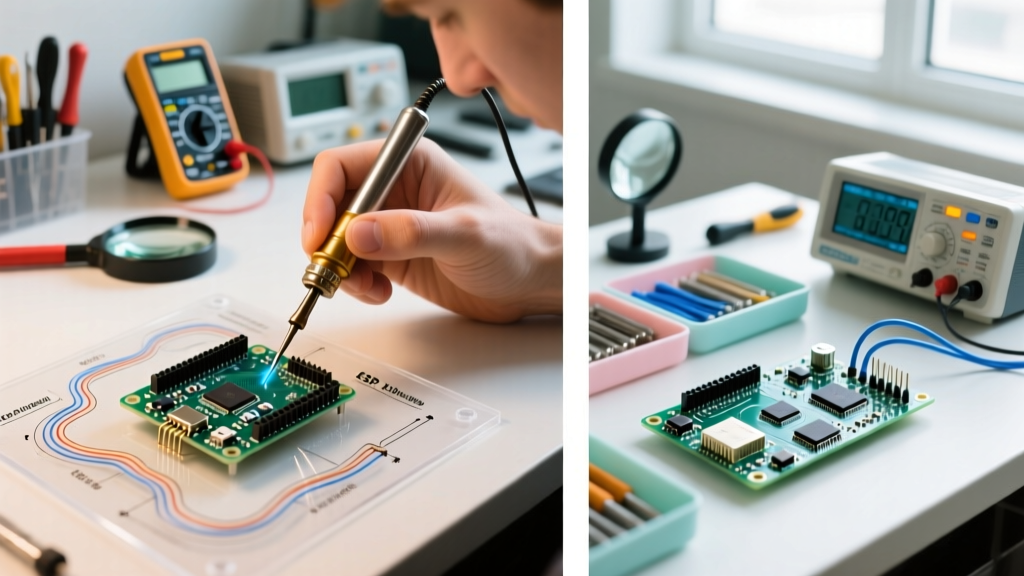
- Grounding Verification: Use a multimeter to check the resistance between the soldering iron tip and the earth ground pin on your power plug. It must read < 2.0 Ω.
- Extractor Placement: Position the fume extractor nozzle exactly 1.5 to 2 inches from the soldering point. Any further, and the thermal plume will escape into the room.
- Flammability Check: Ensure no aerosol cleaners (like contact cleaners or IPA in open dispensers) are within a 2-foot radius of the iron's resting stand.
- Wet Sponge Protocol: If using a brass wire sponge (preferred for thermal shock prevention), ensure it is free of excessive solder clippings that could cause a short circuit if the iron rests too deeply.
Frequently Asked Questions
Is lead-free solder safer for the technician?
From a heavy metal toxicity standpoint, yes. SAC305 eliminates the risk of lead ingestion via hand-to-mouth transfer. However, lead-free solders require higher temperatures, which actually increases the volume of volatile organic compounds (VOCs) and colophony fumes generated by the flux. You must pair lead-free soldering with rigorous fume extraction.
Can I use a soldered connection for high-current automotive wiring?
While soldered connections provide a great electrical bond, pure solder joints in high-vibration automotive environments are prone to fatigue cracking because solder is softer than copper. For automotive applications (e.g., 12V/40A headlight circuits), the industry best practice is to use an adhesive-lined heat shrink crimp connector (e.g., Molex Perma-Seal), using soldering only as a secondary seal if absolutely necessary, though crimping alone is preferred by OEMs.
How often should I replace my fume extractor filters?
It depends on usage volume, but a general rule for HEPA/Gas combination filters in a hobbyist or light professional setting is every 6 to 9 months. If you notice a sweet, pine-like odor returning to your workspace, the activated carbon layer is saturated and must be replaced immediately, as it is no longer adsorbing toxic aldehydes.