
Mastering the Art of Safe Soldering Connections
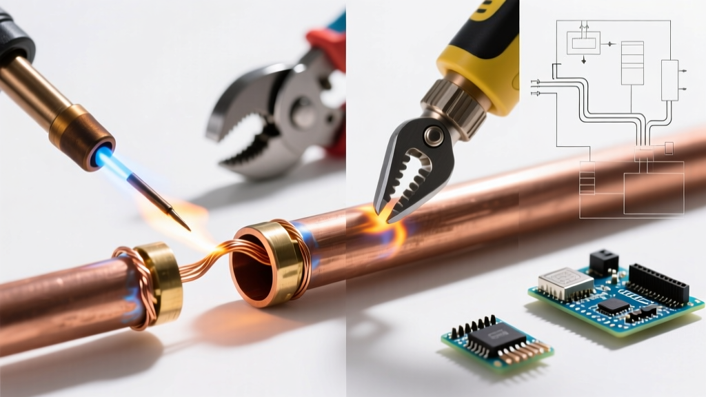
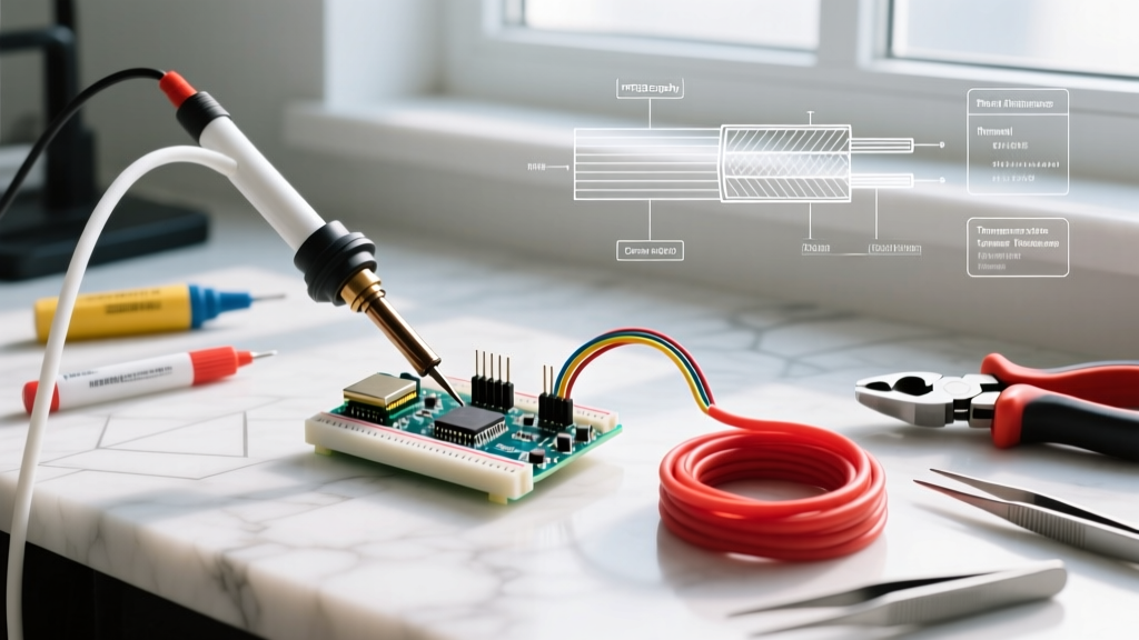
Creating reliable soldering connections is the foundational skill of any electronics enthusiast or professional. However, the pursuit of the perfect solder joint often overshadows the critical safety protocols required to protect both the operator and the sensitive components being assembled. As of 2026, the widespread adoption of lead-free alloys and high-temperature fluxes has shifted the hazard landscape, making modern safety best practices more important than ever. This guide dives deep into the thermal, chemical, and electrical safety protocols necessary for producing robust soldering connections without compromising your health or your hardware.
The Hidden Hazards of Soldering Connections
When evaluating the safety of soldering connections, we must categorize risks into three distinct domains: chemical exposure, thermal damage, and electrostatic discharge (ESD). Understanding the exact failure modes and health risks in each category is the first step toward mitigation.
Chemical Exposure: The Rosin Threat
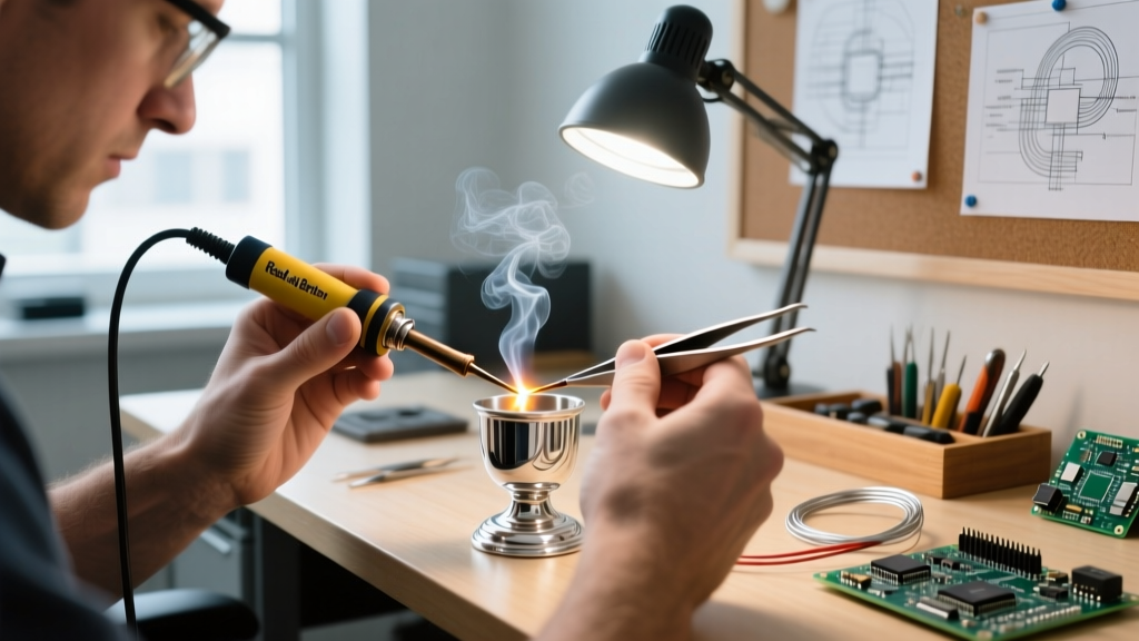
The most pervasive danger in soldering is not the metal alloy, but the flux. Traditional rosin-based fluxes contain colophony (abietic acid). When heated to the 300°C+ temperatures required for soldering connections, colophony vaporizes and oxidizes, creating a complex aerosol of aliphatic aldehydes and acid gases. According to the UK Health and Safety Executive (HSE), repeated exposure to rosin fumes is a leading cause of occupational asthma and severe respiratory sensitization. Once sensitized, even microscopic traces of flux fumes can trigger debilitating asthma attacks.
Thermal and Component Damage
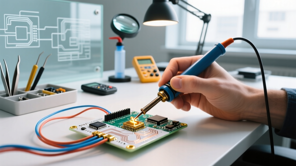
Excessive heat application doesn't just burn the operator; it destroys the PCB. The IPC-J-STD-001 standard strictly governs the thermal profiles for soldering connections. Exceeding a dwell time of 3 to 4 seconds per joint on standard FR-4 boards risks pad delamination, via barrel cracking, and internal component thermal shock. Conversely, insufficient heat leads to 'cold joints'—grainy, high-resistance connections that can cause localized thermal runaway and eventual fire hazards in high-current circuits.
Workspace Setup and Fume Extraction Matrix
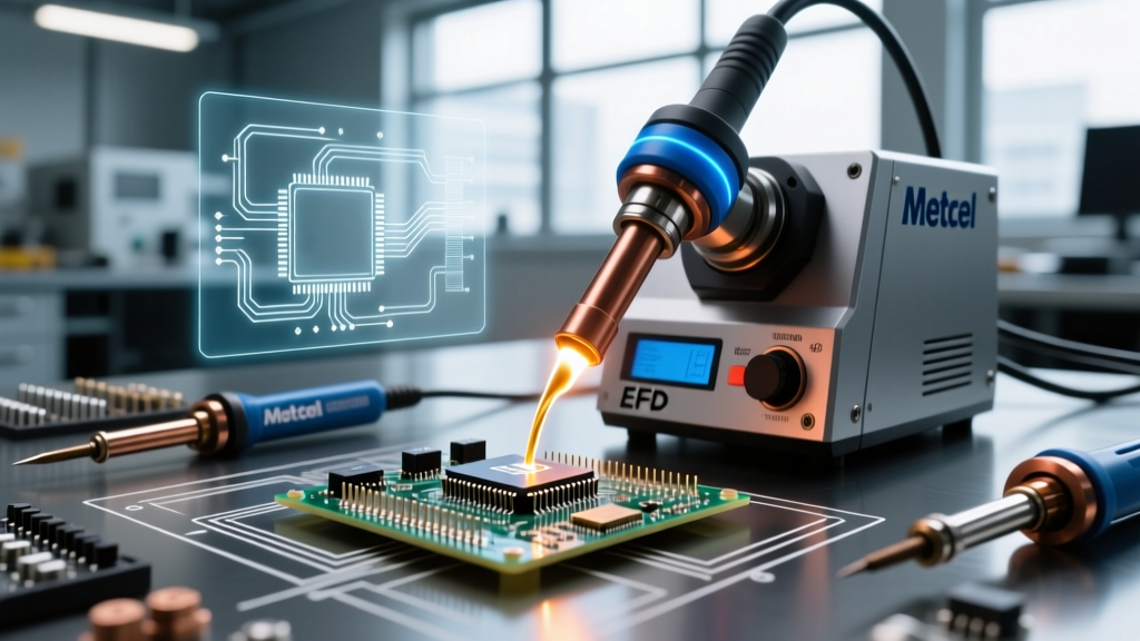
Proper ventilation is non-negotiable. Relying on a standard desk fan to blow fumes away merely redistributes hazardous particulates around your breathing zone. You need active, localized exhaust ventilation (LEV) equipped with HEPA and activated carbon filters to capture both particulate matter and volatile organic compounds (VOCs).
| Fume Extractor Model | Filtration Type | Airflow (CFM) | Est. 2026 Price | Best Use Case |
|---|---|---|---|---|
| Hakko FA-400 | HEPA + Carbon | 34 CFM | $145 - $160 | Benchtop DIY & Light Repair |
| Edsyn FUME-X | Multi-stage Carbon | 45 CFM | $280 - $320 | Continuous Production / Heavy Flux |
| Velleman VTSS5 | Basic Carbon Pad | 18 CFM | $45 - $60 | Occasional Hobbyist (Low Budget) |
For professional or frequent DIY environments, the Hakko FA-400 remains the gold standard due to its easily replaceable filter cartridges and quiet motor operation. Always position the extraction hood within 6 to 8 inches of the soldering iron tip to ensure optimal capture velocity.
Electrical Safety and ESD Protection
When forming soldering connections on modern microcontrollers, FPGAs, or MOSFETs, Electrostatic Discharge (ESD) is a silent killer. The human body can easily accumulate static charges exceeding 3,000V simply by moving in a low-humidity environment. Many modern logic gates and RF components can be permanently degraded or destroyed by ESD strikes as low as 50V—well below the threshold of human perception.
Expert Insight: 'Grounding your soldering iron is just as critical as grounding yourself. An ungrounded iron tip can float to dangerous AC leakage voltages, instantly punching through the gate oxide of a sensitive FET. Always verify tip-to-ground resistance is below 2 ohms before working on bare die or exposed CMOS circuitry.'
To align with the ESD Association ANSI/ESD S20.20 standards, your workspace must incorporate the following:
- Dissipative Matting: Use a dual-layer rubber mat (e.g., 3M 4200 series) with a surface resistance of 10^6 to 10^8 ohms. This safely bleeds off static charges without creating a short-circuit hazard if a live board is dropped on it.
- Wrist Straps: A 1-megohm current-limiting resistor wrist strap connected to a dedicated common point ground. Never clip directly to a grounded metal pipe without a resistor, as this creates a lethal shock hazard if you accidentally touch mains voltage.
- Isolation Transformers: When troubleshooting live AC/DC power supplies, an isolation transformer prevents the ground loop from completing through your body and your grounded soldering station.
Thermal Profiling for Optimal Connections
Achieving safe and reliable soldering connections requires matching your iron's temperature profile to the specific alloy and thermal mass of the joint. As of 2026, the most common alloys encountered are Sn63/Pb37 (Eutectic) and SAC305 (Lead-Free).
Alloy-Specific Temperature Guidelines
- Sn63/Pb37 (63/37 Leaded): Melts at 183°C. Set your station (e.g., Weller WES51 or Hakko FX-888D) to 315°C - 330°C. This provides a superheat of ~130°C, ensuring rapid wetting without excessive dwell time.
- SAC305 (Lead-Free): Melts at 217°C. Requires higher thermal energy. Set your station to 350°C - 375°C. Use chisel tips with high thermal mass (like the Hakko T18-C4) to prevent the tip temperature from crashing when it contacts a large ground plane.
- SN100C (Lead-Free Alternative): Melts at 227°C. Offers better wetting than SAC305 and reduces copper pad erosion. Set station to 340°C - 360°C.
According to Cornell University Environmental Health and Safety, maintaining strict temperature control not only protects the board but also minimizes the thermal degradation of the flux, which in turn reduces the volume of hazardous fumes generated during the soldering process.
Step-by-Step Safe Connection Protocol
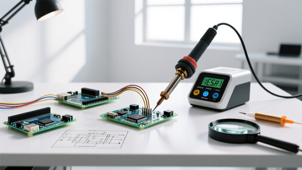
Follow this standardized workflow to ensure every soldering connection is mechanically sound, electrically reliable, and safely executed.
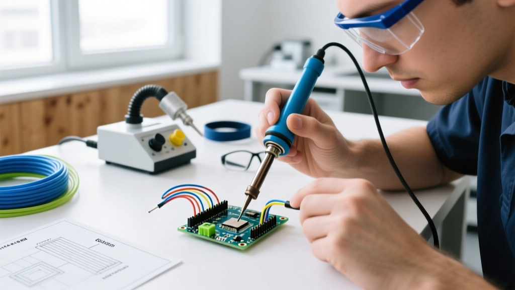
- Preparation: Secure the PCB in a non-conductive vise or board holder. Don your safety glasses (to protect against hot flux spatter) and ESD wrist strap.
- Tin the Tip: Apply a generous amount of cheap, heavily fluxed solder to the iron tip before heating. This creates a thermal bridge and prevents oxidation of the iron plating.
- Heat the Joint, Not the Solder: Apply the iron tip simultaneously to the component lead and the PCB pad. Hold for 1 to 2 seconds to bring both surfaces above the alloy's liquidus temperature.
- Feed the Alloy: Touch the solder wire to the intersection of the pad and lead—not directly to the iron tip. Capillary action will draw the molten solder into the through-hole or around the SMD pad.
- Remove and Inspect: Withdraw the solder wire first, then the iron. Allow the joint to cool naturally for 2-3 seconds. Do not blow on the joint, as rapid cooling induces micro-fractures and cold joint crystallization.
- Clean (If Required): If using a water-soluble flux, clean the board with 99% isopropyl alcohol or a dedicated saponifier within 4 hours to prevent corrosive dendrite growth.
Frequently Asked Questions (FAQ)
Is it safe to use leaded solder at home?
Yes, provided you follow basic hygiene protocols. The primary risk of leaded solder (Sn63/Pb37) is ingestion, not inhalation, as lead does not vaporize at standard soldering temperatures (315°C). Wash your hands thoroughly with soap and water after handling leaded solder, and never eat or drink at your soldering bench. The fumes you see are flux, not lead vapor.
How often should I replace my fume extractor filters?
For a hobbyist soldering 5-10 hours a week, replace the activated carbon and HEPA filters every 6 to 9 months. If you notice a sweet, acrid smell escaping the exhaust, the carbon bed is saturated and must be replaced immediately. Most professional units feature an LED indicator that tracks actual motor run-time.
What causes a solder joint to look dull and grainy?
A dull, grainy, or 'frosted' appearance is the hallmark of a cold joint or a disturbed joint. This occurs when the components move before the solder has fully solidified, or if the iron temperature was too low to properly activate the flux and wet the copper. Cold joints have high electrical resistance and can cause intermittent circuit failures or localized overheating.