
The Problem with Generic Soldering Advice
Walk into any electronics forum or hardware store, and you will hear sweeping generalizations: 'always use 60/40 for electronics' or 'lead-free is mandatory for everything.' But as any seasoned technician knows, the metallurgy and thermal dynamics of joining two metals depend entirely on the application. When evaluating soldering examples across different industries, it becomes clear that a one-size-fits-all approach leads to cold joints, copper dissolution, and catastrophic field failures.
In 2026, with the continued evolution of high-density PCB layouts and stringent automotive reliability standards, selecting the correct solder alloy, flux chemistry, and thermal profile is more critical than ever. This guide provides a practical decision framework based on real-world soldering examples, helping you match the exact metallurgical solution to your specific engineering or DIY challenge.
The Core Decision Matrix: Matching Alloy to Application
Before diving into specific scenarios, use this matrix as your baseline decision framework. The right choice balances melting point, mechanical strength, wetting action, and environmental compliance.
| Application Scenario | Recommended Alloy | Melting Point | Flux Chemistry | Iron Temp Profile |
|---|---|---|---|---|
| General Purpose / Prototyping | Sn63/Pb37 (Eutectic) | 183°C (361°F) | ROL0 (No-Clean Rosin) | 315°C - 330°C |
| Commercial PCB Assembly (RoHS) | SAC305 (Sn96.5/Ag3.0/Cu0.5) | 217°C - 220°C | Water-Soluble or No-Clean | 350°C - 380°C |
| Automotive Wiring & Connectors | Sn60/Pb40 or Sn96.5/Ag3.5 | 183°C - 221°C | Polyolefin Heat Shrink w/ Adhesive | 330°C - 350°C |
| Copper Plumbing & HVAC | BCuP-5 (Sil-Fos / 15% Silver) | 645°C - 800°C | Self-Fluxing on Copper (or Paste) | Oxy-Acetylene or MAP-Pro Torch |
Soldering Examples in High-Reliability PCB Assembly
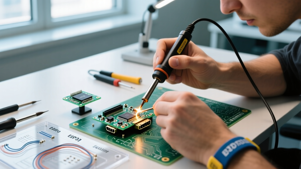
Let us examine one of the most demanding soldering examples: surface mount technology (SMT) and through-hole components on a multi-layer FR4 printed circuit board. Under modern RoHS directives, SAC305 (Tin-Silver-Copper) is the industry standard.
The Intermetallic Compound (IMC) Challenge
When SAC305 melts and contacts a copper pad, an Intermetallic Compound (IMC) layer forms—specifically the Cu6Sn5 and Cu3Sn phases. According to guidelines outlined by the IPC Standards body, a proper IMC layer should be between 1 to 3 microns thick. If your soldering iron is set too high (e.g., above 400°C) or dwell time exceeds 3 seconds, the IMC layer grows too thick, becoming brittle and prone to micro-cracking under thermal cycling.
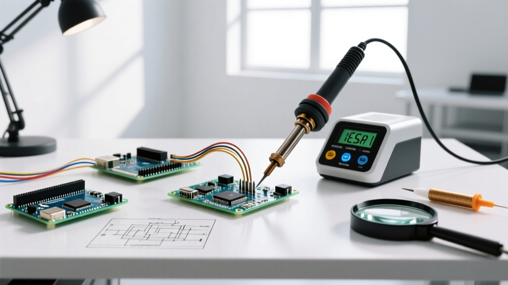
- Tooling Specifics: For SAC305, use a high-thermal-recovery station like the JBC CD-2BQE or Weller WE1010NA with a chisel tip (e.g., Weller ETA or JBC C115-112). Cartridge-style irons are mandatory in 2026 to maintain the 360°C setpoint when hitting large ground planes.
- Cost Factor: Expect to pay between $55 and $65 per pound for high-quality SAC305 0.031" wire with a 2.2% no-clean flux core (such as Kester 245 or Indium Corporation equivalents) in the current market.
Soldering Examples in Automotive Wiring and Harnesses
Automotive environments subject electrical connections to extreme vibration, moisture, and thermal expansion. Evaluating soldering examples in this sector requires referencing the NASA Workmanship Standards and IPC/WHMA-A-620, which dictate that solder alone should never be used as a mechanical strain relief.
The Solder Sleeve vs. Crimp Debate
While crimping is the primary method for automotive harnesses, soldering is still required for specific sensor pigtails and RF shielding. The correct approach uses solder sleeves (heat shrink tubing with a preform ring of Sn60/Pb40 or Sn96.5/Ag3.5 solder and an inner layer of thermoplastic adhesive).
- Strip the wires and twist the strands lightly (do not over-twist, which prevents capillary action).
- Slide the solder sleeve over the joint.
- Apply heat evenly with a heat gun (set to 250°C) until the solder ring melts and flows, and the adhesive extrudes slightly from the ends.
Expert Warning: Never use acid-core plumbing flux on automotive wiring. The chloride residues will rapidly corrode the copper strands, leading to high-resistance failures within months. Always use rosin-core or rely on the flux embedded in solder sleeves.
Soldering Examples in Plumbing and Refrigeration
Transitioning from micro-electronics to macro-mechanical joints, plumbing and HVAC soldering examples rely on entirely different metallurgy. Here, we are dealing with capillary action in 1/2" to 2" copper pipes, requiring high-temperature brazing or silver-bearing soldering.
Sil-Fos and BCuP Alloys
For copper-to-copper joints in refrigeration lines, technicians use BCuP alloys (commonly known by the brand name Sil-Fos), which contain 5% to 15% silver. The phosphorus in the alloy acts as a self-fluxing agent on pure copper, eliminating the need for external chemical fluxes that could contaminate the refrigerant system.
- Thermal Requirement: A standard 60W soldering iron is useless here. You need an oxy-acetylene torch or a high-BTU MAP-Pro torch to bring the copper mass up to the 700°C+ flow point.
- Flux Exception: If you are joining copper to brass or stainless steel in a plumbing application, the phosphorus will not self-flux the dissimilar metal. You must apply a specialized white paste flux (zinc chloride-based) to prevent oxidation during heating.
Failure Mode Analysis: What the Examples Teach Us
By studying failed soldering examples in the field, we can build a troubleshooting framework for common defects. The Indium Corporation and other metallurgical labs frequently document these failure modes:
1. Tin Whiskers (The Lead-Free Curse)
Pure tin and high-tin lead-free alloys (like SAC305) are susceptible to tin whiskers—microscopic, conductive crystalline structures that grow over time and cause short circuits. Decision: If you are building aerospace or medical life-support electronics where long-term reliability is non-negotiable, you must use a conformal coating (like acrylic or urethane) to physically suppress whisker growth, or seek an exemption to use Sn63/Pb37, as the addition of lead effectively prevents whisker formation.
2. Copper Dissolution (Leaching)
When using high-silver solders (like Sn96.5/Ag3.5) on thin-film PCB pads, the silver aggressively scavenges copper from the pad, a phenomenon known as leaching. This results in a weak, pitted joint. Decision: Limit dwell time to under 2 seconds and use a copper-silver alloy (SAC305) rather than a pure tin-silver alloy to slow the dissolution rate.
3. Disturbed Joints (The 'Frosted' Look)
A eutectic alloy like Sn63/Pb37 transitions instantly from liquid to solid at 183°C. However, non-eutectic alloys (like Sn60/Pb40 or SAC305) have a 'pasty' or plastic range. If the component is moved while the joint is in this pasty phase, the IMC matrix fractures, resulting in a dull, frosted, or grainy appearance. Decision: Use mechanical jigs or holding tools to ensure absolute zero movement during the 3-to-5-second cooling phase.
Summary: Building Your Own Framework
The most effective way to master joining technologies is to analyze diverse soldering examples and extract the underlying metallurgical principles. Whether you are selecting a $60 spool of SAC305 for a BGA rework station, choosing a solder sleeve for an automotive ECU harness, or brazing a copper refrigerant line, the decision always comes down to three variables: the base metals being joined, the thermal mass of the assembly, and the environmental stresses the joint will endure in the field. Keep this framework handy, and your joints will consistently pass both visual inspection and long-term reliability testing.