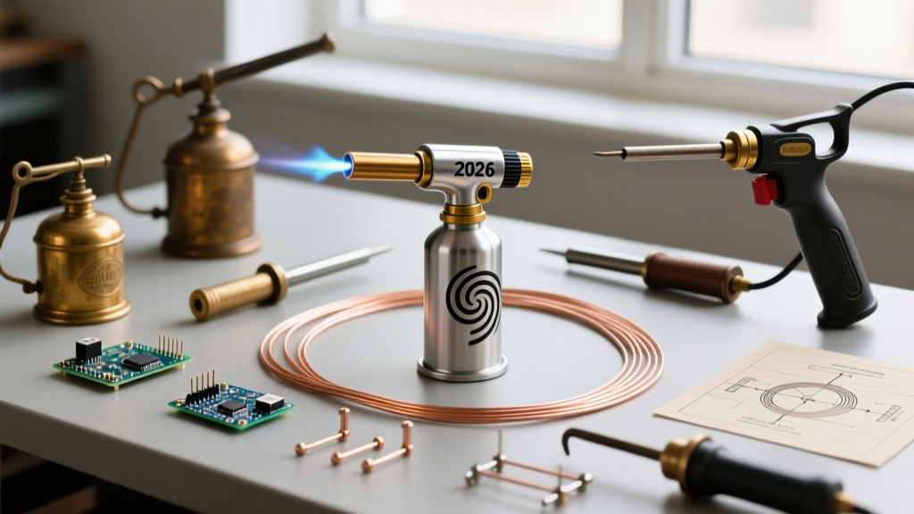
Clarifying the Terminology: What is 'Lead Wire'?
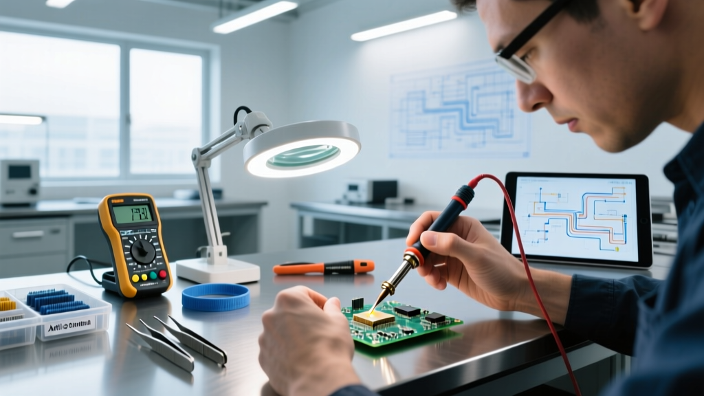
In the electronics and DIY community, the term lead wire for soldering can cause confusion. Beginners often mistake it for solder wire containing the chemical element lead (Pb). However, in professional assembly and prototyping, 'lead wire' refers to the insulated hookup wires, jumper wires, or component tails used to create electrical connections between PCB pads, terminals, and breadboards. Choosing the correct lead wire is just as critical as selecting the right soldering iron or flux. A mismatched wire gauge or inadequate insulation material will result in melted jackets, solder wicking, and catastrophic joint failures.
This comprehensive guide breaks down the exact specifications you need to select, prepare, and solder lead wires for any project, from delicate SMD rework to high-current power distribution.
Decoding Wire Insulation Materials for Soldering
The insulation jacket is the first line of defense against heat and short circuits. When your soldering iron tip (often hovering between 320°C and 380°C) accidentally grazes the wire, the insulation's thermal tolerance dictates whether it survives or melts into a toxic, sticky mess. According to IPC wiring standards, selecting the right dielectric material is mandatory for reliable assemblies.
| Insulation Type | Max Continuous Temp | Solder Iron Resistance | Avg Cost (100ft Spool) | Best Application |
|---|---|---|---|---|
| Silicone | 200°C - 300°C | Excellent (Iron won't melt it) | $15 - $25 | General prototyping, RC models, high-temp environments |
| PVC (Polyvinyl Chloride) | 80°C - 105°C | Poor (Melts/shrinks instantly) | $10 - $18 | Basic breadboarding, low-temp chassis wiring |
| PTFE (Teflon) | 260°C - 300°C | Exceptional (Zero melt-back) | $40 - $85 | Aerospace, MIL-SPEC, high-density PCB jumpers |
| Enamel (Magnet Wire) | 150°C - 220°C | Moderate (Burns off with heat/flux) | $8 - $15 | Coils, transformers, tight-space micro-jumpers |
Expert Recommendation: For 90% of DIY and prototyping scenarios, silicone-insulated wire is the undisputed champion. Its high strand count (often 100+ strands of 0.08mm tinned copper) makes it incredibly flexible, and the silicone jacket will not melt even if you rest a 360°C iron directly on it. Reserve PTFE for high-density surface-mount jumper wires where millimeter precision is required and insulation shrinkback cannot be tolerated.
AWG Sizing: Matching Lead Wire to Current and Pads
American Wire Gauge (AWG) defines the physical thickness of the copper conductor. Using a wire that is too thick for a PCB pad will cause pad lifting during prolonged heating. Using a wire that is too thin for a power rail will result in voltage drop and overheating. As outlined in SparkFun's Working with Wire tutorial, matching AWG to the physical footprint is crucial.
The 2026 AWG Selection Framework
- 30 AWG to 28 AWG (0.25mm - 0.32mm): Ultra-thin. Use for SMD jumper wires, 0402/0603 component rework, and wrapping around microcontroller GPIO pins. Requires a micro-soldering tip (e.g., Hakku T12-IL or JBC C115-107) and precise 63/37 Sn/Pb solder (0.3mm diameter).
- 26 AWG to 24 AWG (0.40mm - 0.51mm): The standard for through-hole components, breadboard jumpers, and general PCB signal routing. Fits perfectly into standard 0.8mm to 1.0mm plated through-holes (PTH).
- 22 AWG to 20 AWG (0.64mm - 0.81mm): Ideal for power rails, battery leads, and terminal block connections. Carries 5A to 7A safely. Do not attempt to force 20 AWG into standard IC DIP sockets; it will bend the pins.
- 18 AWG to 14 AWG (1.02mm - 1.63mm): Strictly for high-current distribution (e.g., LiPo battery harnesses, ESC connections, mains wiring). Requires a high-wattage iron (65W+) or a dedicated soldering torch to achieve proper wetting without cold joints.
Stranded vs. Solid Core: Which Lead Wire to Choose?
The physical construction of the copper core drastically alters how the wire behaves during and after soldering.
Solid Core Lead Wire
Consists of a single, solid copper cylinder.
Pros: Holds its shape perfectly (great for breadboard insertion); easier to strip with automated machines; solder flows evenly around the outside diameter.
Cons: Prone to work hardening and snapping if bent repeatedly (fatigue failure); difficult to route in tight enclosures.
Stranded Lead Wire
Composed of multiple thin copper threads twisted together.
Pros: Highly flexible; resists vibration and mechanical fatigue; provides a larger surface area for solder wetting via capillary action.
Cons: Strands can fray during stripping; requires 'tinning' to prevent fraying before insertion into screw terminals; can wick solder too far up the wire if over-heated.
Pro-Tip for Stranded Wire: Never use stranded lead wire for breadboarding. The frayed strands will catch inside the breadboard contacts, ruining both the wire and the breadboard's internal leaf springs. Always use solid core (usually 22 AWG) for solderless breadboards, and stranded silicone for soldered PCB connections.
Step-by-Step: Prepping and Tinning Lead Wires
Proper preparation prevents poor performance. The goal of 'tinning' is to coat the bare copper strands with a thin layer of solder, binding them into a solid mass that mimics solid-core wire. Here is the exact procedure used by IPC-certified technicians:
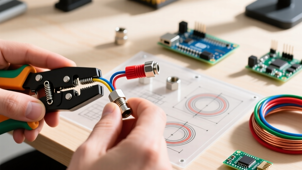
- Precision Stripping: Strip exactly 3mm to 5mm of insulation. Use a high-quality stripper like the Knipex TwinStrip 12 42 195 or Hakko CHP 170 micro-shears. Avoid crushing the copper strands, which increases electrical resistance.
- Mechanical Twist: Gently twist the exposed strands at a 15-degree angle to align them. Do not over-twist, which can cause the wire to become rigid and snap.
- Flux Application: Apply a small amount of tacky flux (e.g., MG Chemicals 8341 or Amtech NC-559-V2-TF) to the bare copper. Flux removes oxidation and promotes capillary action.
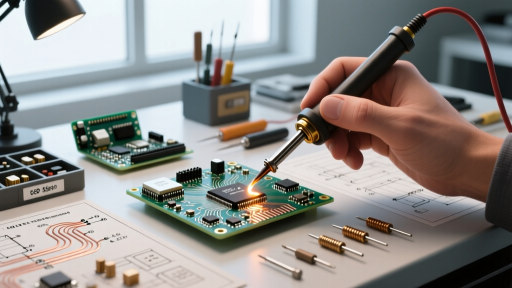
- Heat Transfer: Set your soldering station to 320°C for leaded solder (63/37) or 360°C for lead-free (SAC305). Tin the iron tip, then touch the tip to the side of the wire, not the top.
- Solder Feed: Feed 0.8mm diameter solder wire to the junction of the iron tip and the copper. Capillary action will draw the solder between the strands. Stop feeding the moment the solder reaches the edge of the insulation.
- Inspection: A properly tinned lead wire will have a smooth, shiny, concave fillet. You should still see the outline of the strands (a 'grainy' look means insufficient heat or lack of flux).
Common Failure Modes and Edge Cases
Even experienced makers encounter issues when working with specific lead wires. Here is how to troubleshoot the most common edge cases:
1. Solder Wicking Under the Insulation
The Problem: Solder travels up the stranded wire and hardens beneath the PVC or silicone jacket, making the wire stiff and prone to snapping right at the joint.
The Fix: Implement the '1mm Gap Rule'. Strip the wire 1mm further than your intended tin length. Tin the wire, then use flush cutters to snip off the excess untinned copper. Alternatively, switch to PTFE wire, which has zero capillary wicking properties due to its low surface energy.
2. Insulation Shrinkback (The 'Turtle Neck' Effect)
The Problem: When heat is applied, PVC insulation shrinks backward, exposing bare copper and risking short circuits on dense PCBs.
The Fix: Never use standard PVC for high-density SMD jumper wires. If you must use PVC, apply heat-shrink tubing (e.g., 2:1 ratio polyolefin) over the joint immediately after soldering, or switch to extruded PTFE wire which is dimensionally stable up to 300°C.
3. Cold Joints on High-AWG Power Leads
The Problem: When soldering 14 AWG or 12 AWG lead wires to large XT60 connectors or thick PCB planes, the solder forms a dull, grainy, spherical blob that easily pulls out.
The Fix: A standard 45W iron cannot overcome the thermal mass of thick copper. You must use a high-thermal-mass tip (like a JBC C245-945 chisel) on a 130W+ station, or pre-heat the connection area with a hot air gun at 200°C before applying the iron. Always use a heavy-duty, high-rosin flux (RMA) to prevent rapid oxidation at high temperatures.
Frequently Asked Questions (FAQ)
Can I use aluminum lead wire for soldering electronics?
No. Standard tin/lead and SAC305 solders do not wet aluminum due to its instant-forming oxide layer. While specialized zinc-based solders and aggressive acids exist for aluminum, they are strictly prohibited in electronics due to severe corrosion risks. Always use 99.9% pure copper or tinned copper lead wires.
Does the color of the wire insulation affect solderability?
The color dye itself does not affect solderability, but the base material does. However, for professional assemblies adhering to industry wiring color codes, using specific colors (Red for VCC, Black for GND, Yellow for Data) drastically reduces troubleshooting time and prevents reverse-polarity catastrophic failures.
How long does tinned lead wire last before oxidizing?
A properly tinned copper wire stored in a dry, room-temperature environment will remain easily solderable for 3 to 5 years. If the tinned surface turns dull gray or chalky white, the tin has oxidized. Simply apply fresh flux and re-melt the joint with your iron to restore the metallurgical bond.